Powermax30 XP Service Manual 808150 Revision 0 79
5 – Troubleshooting and System Tests
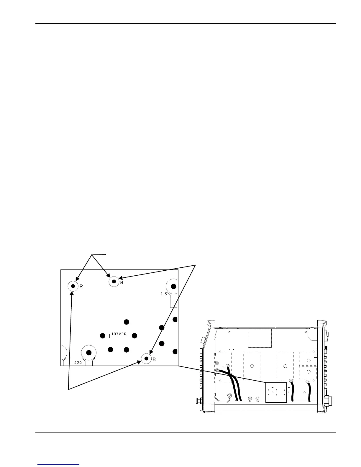
5. Measure the voltage from W to R. (See Figure 18.)
a. Position the test hooks on W and R on the power board.
b. Turn the power ON (I).
c. The multimeter should read 375 VDC.
If you get a value other than 375 VDC, multiply the reading by 0.00601 to convert it to millivolts. Test pin 21 on J7.
(See Test 2 – power board voltage checks on page 76.) If the values match, it is a normal reading.
6. Measure the voltage from W to B.
a. Turn the power OFF (O).
b. Move the test hooks to W and B.
c. Turn the power ON (I).
d. This value should be 187.5 VDC or one-half of the value found in step 5.
7. Measure the voltage from R to B.
a. Turn the power OFF (O).
b. Move the test hooks to R and B.
c. Turn the power ON (I).
d. This value should be 187.5 VDC or one-half of the value found in step 5.
8. The values found in step 6 and step 7 should be approximately equal. If they differ by more than 30 V, replace the
power board.
Figure 18