Chapter 8 Parameter
POWER CON
PCON-CB/LC
181
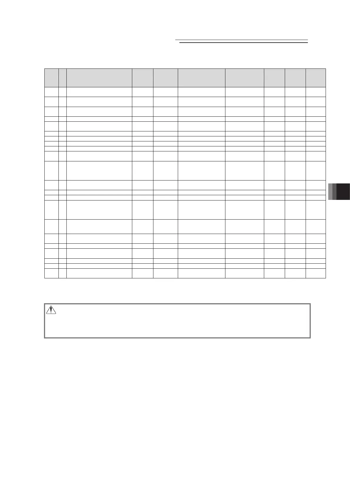
I/O Parameter List (Continued)
No.
Category
Name Symbol Unit Input Range
Default factory
setting
for
Positioner
Mode
for Pulse
Train
Mode
Relevant
sections
140 B IP address IPAD –
0.0.0.0 to
255.255.255.255
Separate volume
{ {
Separate
volume
141 B Subnet mask SNMK –
0.0.0.0 to
255.255.255.255
Separate volume
{ {
Separate
volume
142 B Default gateway DFGW –
0.0.0.0 to
255.255.255.255
Separate volume
{ {
Separate
volume
143 B Overload level ratio OLWL % 50 to 100 100
{
8.2 [77]
144 B
Gain scheduling upper limit
multiplying ratio
GSUL % 0 to 1023 0
{
8.2 [78]
145 C GS velocity loop proportional gain GSPC – 1 to 30000 750
{
8.2 [79]
146 C GS velocity loop integral gain GSIC – 1 to 500000 4500
{
8.2 [80]
147 B Total movement count threshold TMCT Times 0 to 999999999 0 (Disabling)
{
8.2 [81]
148 B Total operated distance threshold ODOT m 0 to 999999999 0 (Disabling)
{ {
8.2 [82]
149 B Zone output changeover FPIO –
0: To change
1: Not to change
0
{
8.2 [83]
151 B
Light malfunction alarm output
select
OALL –
0: Overload warning
output
1: Message lebel alarm
output
0
{ {
9.2 [84]
152 B High output setting BUEN –
0: Disabling
1: Enabling
In accordance with
actuator
(Note2)
{ {
8.2 [85]
153 B BU velocity loop proportional gain BUPC – 1 to 10000 200
{
8.2 [86]
154 B BU velocity loop integral gain BUIC – 1 to 100000 4000
{
8.2 [87]
155 A Absolute battery retention time AIP –
0: 20 days
1: 15 days
2: 10 days
3: 5 days
0
{
8.2 [88]
156 B
Torque check/Light malfunction
output select
SLAL –
0: Torque check effective
1: Light malfunction
effective
0
{ {
8.2 [89]
159 B
FB half direct mode speed unit
(Note 4)
FBVS –
0: Units of 1mm/s
1: Units of 0.1mm/s
Separate volume
{
Separate
volume
165 B Delay time after shutdown release SDDT msec 0 to 100 0
{ {
8.2 [92]
166 B
Startup current limit extension
feature
DCET –
0: Disabling
1: Enabling
In accordance with
actuator
(Note2)
{ {
8.2 [93]
167 B Pulse train datum position RPOS mm -9999.99 to 9999.99 0
{
8.2 [94]
168 B Collision detection feature CODT – 0 to 7 0
{ {
8.2 [95]
182 B
Automatic current reduction feature
select
ACDS –
0: Disabling
1: Enabling
0
{
6.2
Note 2 The setting values vary in accordance with the specification of the actuator. At shipment, the
parameters are set in accordance with the specification.
Note 4 These parameters are exclusively used for the fieldbus type.
Caution: Make sure to set to “Positioner Mode” (No. 25 PIO Pattern = 0 to 5) when performing
an operation with using the serial communication.
If it happens to be in the “pulse train mode” by mistake, the controller may operate
erratically because it is operated according to the “pulse train mode” parameters.

 Loading...


