Chapter 2 Wiring
POWER CON
PCON-CB/LC
39
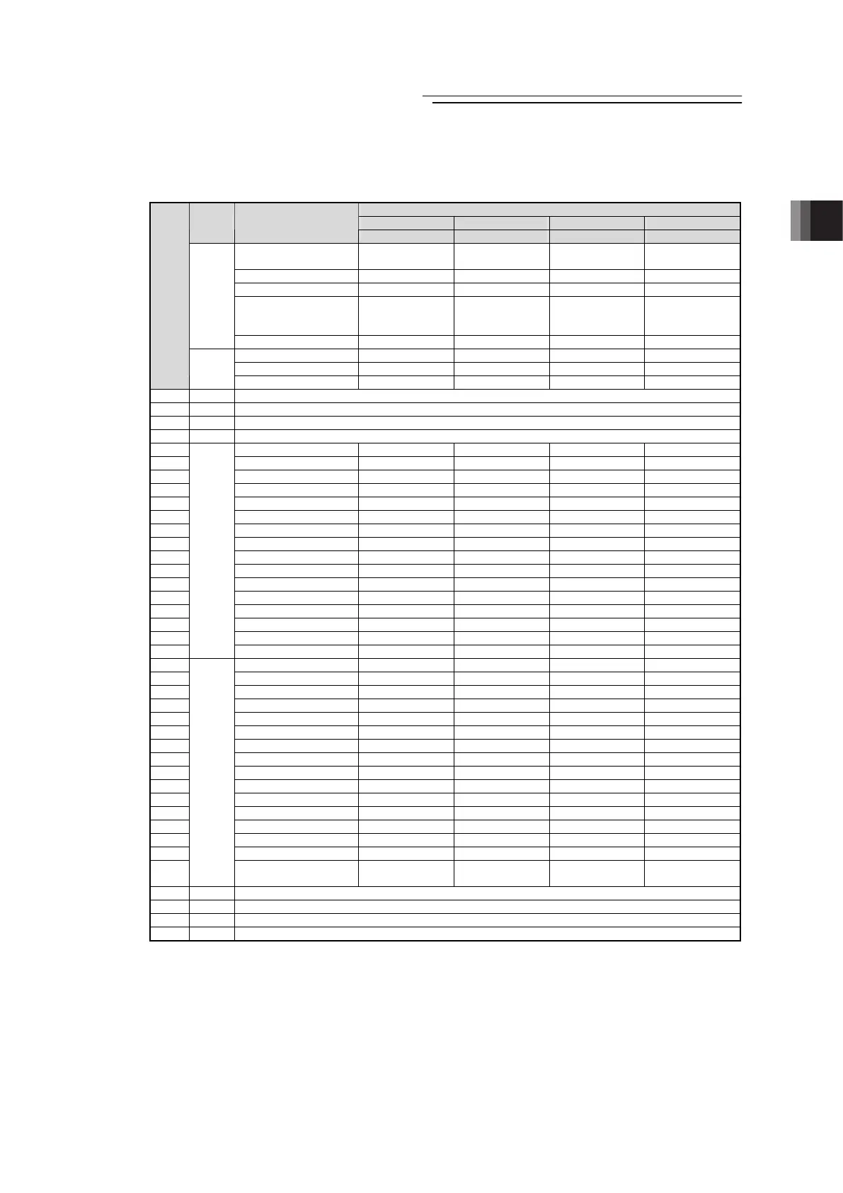
(2) PIO Patterns and Signal Assignment
The signal assignment of I/O flat cable by the PIO pattern is as shown below. Follow the
following table to connect the external equipment (such as PLC).
Parameter No.25 “PIO Pattern” Selection
0 1 2 3
Category
PIO Functions
Positioning mode Teaching mode 256-point mode 512-point mode
Number of positioning
points
64 points 64 points 256 points 512 points
Home return signal { { { {
Jog signal × { × ×
Teaching signal
(Current position
writing)
× { × ×
Input
Brake release { × { {
Moving signal { { × ×
Zone signal { ∆
(Note 1)
∆
(Note 1)
×
Pin
No.
Output
Position zone signal { { { ×
1A 24V P24
2A 24V P24
3A – –
4A – –
5A IN0 PC1 PC1 PC1 PC1
6A IN1 PC2 PC2 PC2 PC2
7A IN2 PC4 PC4 PC4 PC4
8A IN3 PC8 PC8 PC8 PC8
9A IN4 PC16 PC16 PC16 PC16
10A IN5 PC32 PC32 PC32 PC32
11A IN6 – MODE PC64 PC64
12A IN7 – JISL PC128 P128
13A IN8 – JOG+ – PC256
14A IN9 BKRL JOG- BKRL BKRL
15A IN10 RMOD RMOD RMOD RMOD
16A IN11 HOME HOME HOME HOME
17A IN12 *STP *STP *STP *STP
18A IN13 CSTR CSTR/PWRT CSTR CSTR
19A IN14 RES RES RES RES
20A
Input
IN15 SON SON SON SON
1B OUT0 PM1(ALM1) PM1(ALM1) PM1(ALM1) PM1(ALM1)
2B OUT1 PM2(ALM2) PM2(ALM2) PM2(ALM2) PM2(ALM2)
3B OUT2 PM4(ALM4) PM4(ALM4) PM4(ALM4) PM4(ALM4)
4B OUT3 PM8(ALM8) PM8(ALM8) PM8(ALM8) PM8(ALM8)
5B OUT4 PM16 PM16 PM16 PM16
6B OUT5 PM32 PM32 PM32 PM32
7B OUT6 MOVE MOVE PM64 PM64
8B OUT7 ZONE1 MODES PM128 PM128
9B OUT8
(Note1)
PZONE/ZONE2 PZONE/ZONE1 PZONE/ZONE1 PM256
10B OUT9 RMDS RMDS RMDS RMDS
11B OUT10 HEND HEND HEND HEND
12B OUT11 PEND PEND/WEND PEND PEND
13B OUT12 SV SV SV SV
14B OUT13 *EMGS *EMGS *EMGS *EMGS
15B OUT14 *ALM *ALM *ALM *ALM
16B
Output
OUT15
LOAD/TRQS
*ALML
*ALML
LOAD/TRQS
*ALML
LOAD/TRQS
*ALML
17B – –
18B – –
19B 0V N
20B 0V N
(Note) “*” in codes above shows the signal of the active low.
PM1 to PM8 indicate the alarm binary code output signal when an alarm is generated. [Refer to 3.2.3 [7]
Binary Output of Alarm Data Output]
Note 1 The mode can be switched over to PZONE with the setting of Parameter No.149 except for PIO Pattern 3.
(Reference) Signal of Active Low
Signal with “*” expresses the signal of active low. A signal of active low is a signal that the input signal is processed
when it is turned OFF, output signal is ordinarily (or just omit) on while the power is ON, and turns OFF when the signal
is output.

 Loading...


