Chapter 2 Wiring
POWER CON
PCON-CB/LC
40
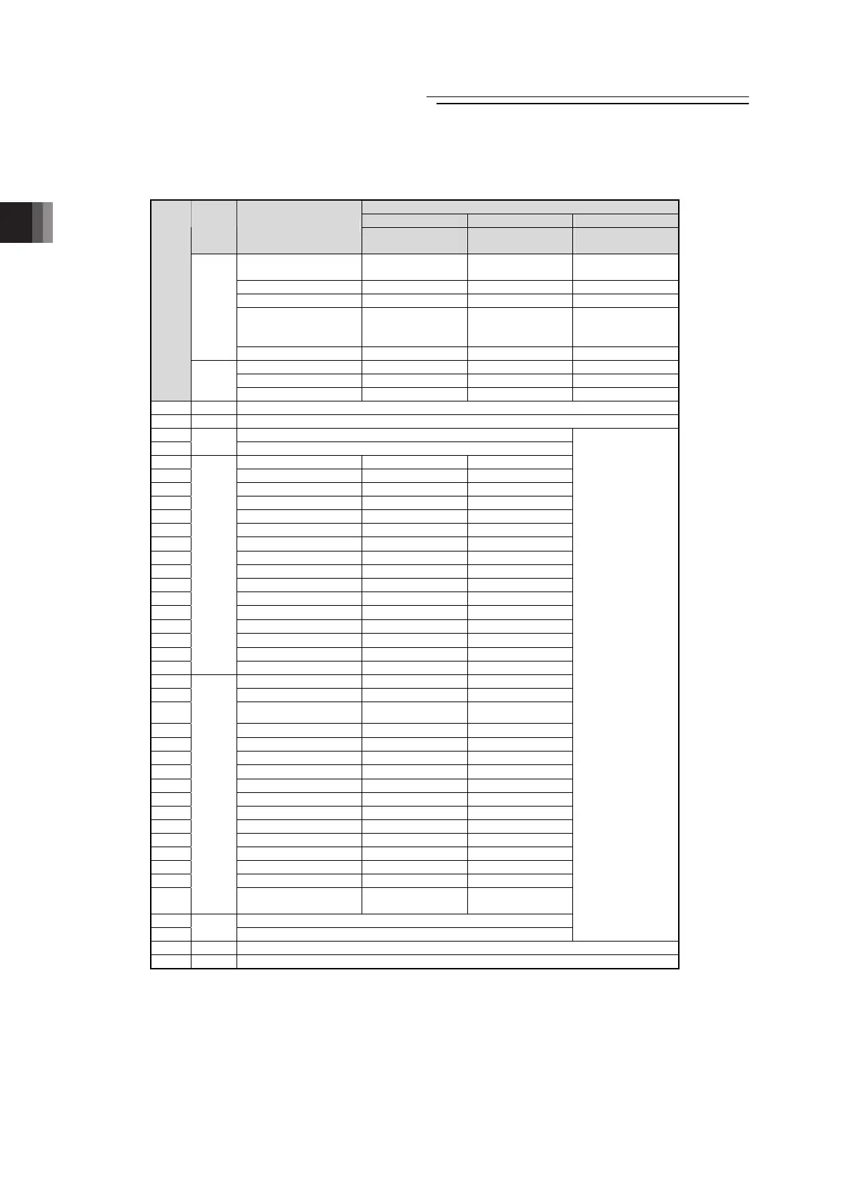
Parameter No.25 “PIO Pattern” Selection
4 5 6 or 7
Category
PIO Functions
Solenoid Valve
Mode 1
Solenoid Valve
Mode 2
Pulse Train Control
Mode
Number of positioning
points
7 points 3 points –
Home return signal { × {
Jog signal × × ×
Teaching signal
(Current position
writing)
× × ×
Input
Brake release { { {
Moving signal × × ×
Zone signal { { {
Pin
No.
Output
Position zone signal { { ×
1A 24V P24
2A 24V P24
3A –
4A
Pulse
input
–
5A IN0 ST0 ST0
6A IN1 ST1 ST1(JOG+)
7A IN2 ST2 ST2
(Note 2)
8A IN3 ST3 –
9A IN4 ST4 –
10A IN5 ST5
–
11A IN6 ST6
–
12A IN7
–
–
13A IN8
–
–
14A IN9 BKRL BKRL
15A IN10 RMOD RMOD
16A IN11 HOME
–
17A IN12 *STP
–
18A IN13
–
–
19A IN14 RES RES
20A
Input
IN15 SON SON
1B OUT0 PE0 LS0
2B OUT1 PE1 LS1(TRQS)
3B OUT2 PE2 LS2
(Note 2)
4B OUT3 PE3
–
5B OUT4 PE4
–
6B OUT5 PE5
–
7B OUT6 PE6
–
8B OUT7 ZONE1 ZONE1
9B OUT8
(Note1)
PZONE/ZONE2 PZONE/ZONE2
10B OUT9 RMDS RMDS
11B OUT10 HEND HEND
12B OUT11 PEND –
13B OUT12 SV SV
14B OUT13 *EMGS *EMGS
15B OUT14 *ALM *ALM
16B
Output
OUT15
LOAD/TRQS
*ALML
*ALML
17B –
18B
Pulse
input
–
Refer to Section
2.2 for the details
of Pulse Train
Control Mode
19B 0V N
20B 0V N
(Note) Shown in ( ) after the signal names above tell the functions performed before the home-return operation.
“*” in codes above shows the signal of the active low.
PM1 to PM8 indicate the alarm binary code output signal when an alarm is generated. [Refer to 3.2.3 [7]
Binary Output of Alarm Data Output]
Note1 The mode can be switched over to PZONE with the setting of Parameter No.149.
Note2 It is invalid before home-return operation.

 Loading...


