450
Appendix
Appendix
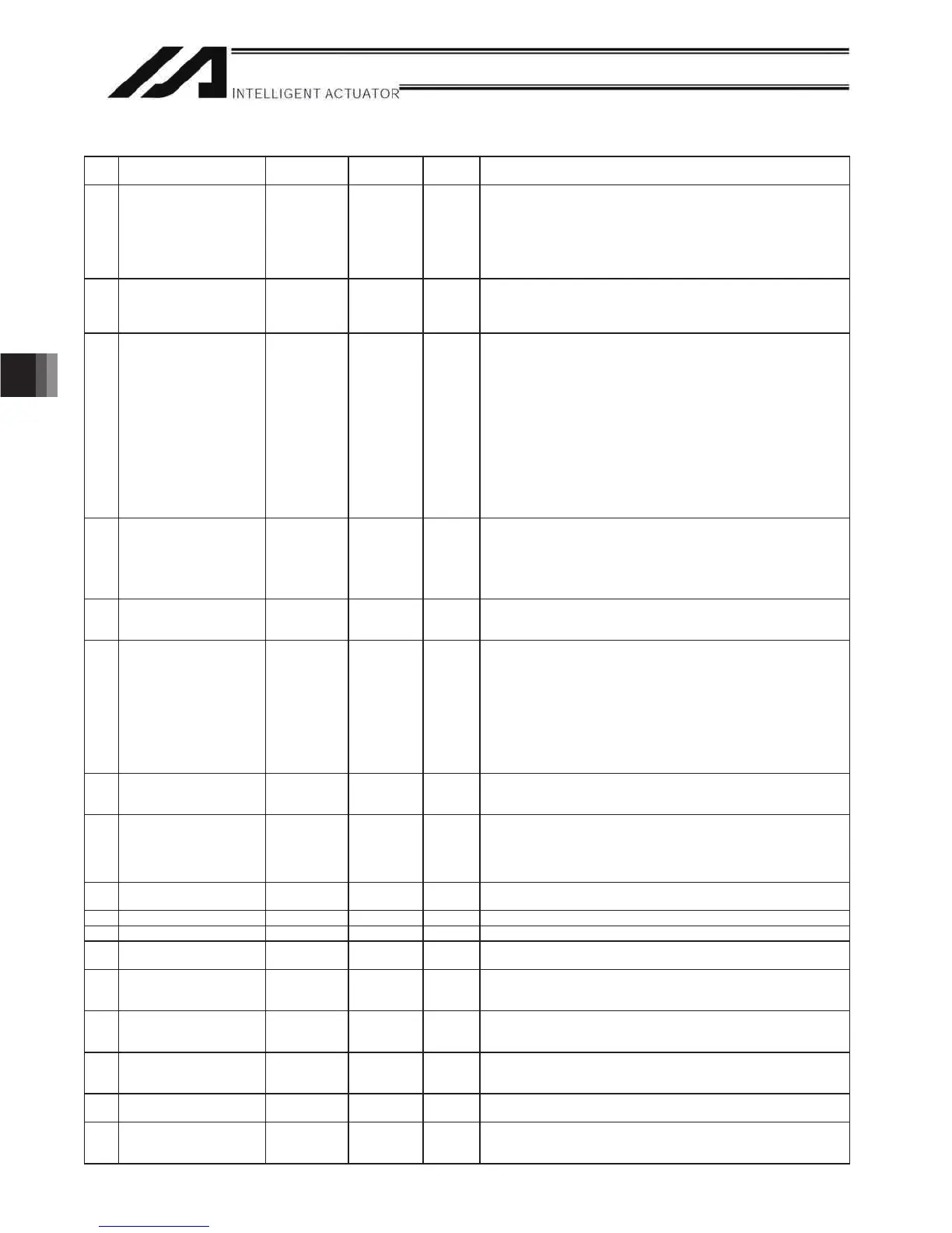
Axis-Specific Parameters
No. Parameter name
Default value
(Reference)
Input range Unit Remarks
102 Synchronizing on/off
Switchover Mating Axis
Number
0 0 to 8 Mutual input necessary (smaller axis number is to be the master axis in a
pair.) Only resolution related same characteristic axes can be selected. It is
invalid to issue a command to a slave axis. (Ineffective at 0)
It is necessary to set the actuators with the synchronizing master and slave
axes matched physically at “home-return end position”.
(Related information: Axis-specific parameter No. 65)
(Main application version 1.17 or later)
103 Brake output control method
select
00
~ 1 0: System Brake Control (for brake control by the system when Each Axis
Parameter No. 34 “Brake Installation Indication” = 1)
1: User Control (User control available in Virtual Output Port No. 7301 to
7306
104 Target axis specification for
multiple-slider near-miss
detection
0H 0H to
FFFFFFFFH
Bits 0 to 3: Mating axis number of near-miss detection target (on the
positive side of the coordinate system of the target axis)
Bits 4 to 7: Mating axis number of near-miss detection target (on the
negative side of the coordinate system of the target axis)
* The mating axis must be entered for each axis.
(Of the pair, the axis with the smaller axis number becomes
the main axis for the sake of convenience.)
* For each axis, only an axis whose resolution and other related
characteristics are the same can be specified as a mating axis.
* In the case of synchro axes, always specify the synchro master
axis. (Specification of the synchro slave axis is prohibited.)
* Specify “0” if no adjacent slider is present on the applicable
side of the coordinate system of the target axis.
(Main application version 0.51 or later)
105 Effective stroke of multiple
sliders
0 0 to 99999999 0.001 mm Set the result of [Inter-slider distance at the farthest position allowed] –
[Inter-slider distance at the closest position allowed] when both axes subject
to multiple-slider near-miss detection are inside the range of operation.
(This parameter is valid only for the master axis between the multiple-slider
axes.)
(Main application version 0.51 or later)
106 Emergency deceleration
margin upon multiple-slider
near-miss detection
5 0 to 999 0.01 G (Main application version 0.51 or later)
107 Multiple-slider setting: Bit
pattern 1
12H 0H to
FFFFFFFFH
Bits 0 to 3: Margin for multiple-slider actual position near-miss detection
(mm)
(Of the multiple sliders, only the parameter for the master axis is
valid.)
(Main application version 0.51 or later)
Bits 4 to 7: Margin for multiple-slider command position nearmiss detection
(mm)
(Of the multiple sliders, only the parameter for the master axis is
valid.)
(Main application version 0.51 or later)
108 Positioning control switching
band for synchro slave axis
5000 1 to 99999 0.001 mm Effective only when specified for the synchro slave axis.
* Related information: Axis-specific parameter No. 52
(Main application version 0.62 or later)
109 Specification of mating
axis for ball-screw spline
correction (linear movement
D[LVURWDWLRQDOPRYHPHQW
axis)
0 0 to 8 This parameter must be entered for both axes.
0: Invalid
1 to 8: Mating axis number
* Related information: Axis-specific parameter No. 1
(Main application version 0.82 or later)
110 to
118
(For expansion) 0 ~
119 FSG 0 0 to 100
120 FFF 10 0 to 100 * Change is prohibited unless instructed by the manufacturer.
121 to
133
(For expansion) 0 ~
134 Maximum Operation Speed
for Each Axis
0 0 to 999 0.01G Ineffective when set to 0 or below. Restriction is to be made regarding All
Axes Parameter No.22 “Maximum Acceleration”.
(XSEL-P/Q/PCT/QCT main application Ver. 1.15 or later)
135 Maximum Operation
Deceleration for Each Axis
0 0 to 999 0.01G Ineffective when set to 0 or below. Restriction is to be made regarding All
Axes Parameter No.23 “Maximum Deceleration”.
(XSEL-P/Q/PCT/QCT main application Ver. 1.15 or later)
136 Minimum Emergency
Deceleration for Each Axis
0 0 to 999 0.01G 0Ineffective when set to 0 or below. Restriction is to be made regarding All
Axes Parameter No.24 “Minimum Emergency Deceleration”.
(XSEL-P/Q/pCT/QCT main application Ver. 1.15 or later)
137 to
140
(For expansion) 0 ~
141 Reference coordinate after
automatic refresh of home
preset value
0 -99999999 to
99999999
0.001 mm
0.001 deg
* Valid only for ball-screw spline axes.
* Related information: Axis-specific parameter Nos. 10, 12, 144
(Main application version 0.82 or later)

 Loading...


