449
Appendix
Appendix
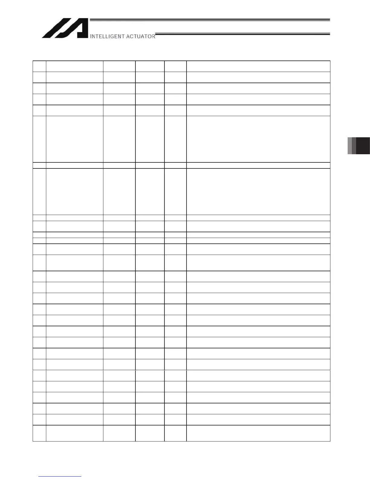
Axis-Specific Parameters
No. Parameter name
Default value
(Reference)
Input range Unit Remarks
72 '5995RIIVHW 0 Reference
only
DRVVR (Change prohibited) To maintain symmetry of the positive and negative
sides.
73 DRVVR – offset 0 Reference
only
DRVVR (Change prohibited) To maintain symmetry of the positive and negative
sides.
74 For future expansion 0 Reference
only
75 For future expansion 0 Reference
only
76 Home-adjustment parameter
set selection
1 Reference
only
(Change prohibited)
0: P21 = Phase-Z evacuation distance at INC home return
P12 = Ideal phase-Z position coordinate
1: P32 is read automatically even when P33 = 0. P33 = 0 indicates “actual
distance.”
P21 = Offset travel at home return
P12 = Coordinate achieved by offset travel at home return
P26 = Invalid
(To facilitate adjustment)
77 Synchro S pulse 3 0 to 99999 Pulse * Related information: Axis-specific parameter No. 52
78 Maximum takeoff command
amount
0 -3000 to 3000 0.001 mm Maximum lift command amount before brake unlock (Input with sign)
(Suppression of momentary drop upon servo ON when a heavy object is
placed)
* Important: Input using the same sign as the rising coordinate direction.
(0.100 mm to 0.500 mm in absolute value as a guideline)
* The servo-ON check time (axis-specific parameter No. 30) must also be
extended (approx. 1000 to 1500 msec) to provide a sufficient time for rise-
direction torque to follow.
(Valid only when installation of brake is specified.)
79 Actual takeoff check distance 5 0 to 3000 0.001 mm Absolute value input
80 Maximum forced-feed range 0 0 to 9999 0.001 mm For reduction of settling time. (Invalid range if “0” is set)
(Approx. 1.000 mm as a guideline)
81 Minimum forced-feed range 200 0 to 9999 0.001 mm
82 Medium forced-feed range 600 0 to 9999 0.001 mm
83 Absolute synchro slave-axis
initialization cancellation
0 0 to 5 Valid only with a synchro slave axis.
84 Maximum synchronization
correction speed of synchro
slave axis
5 0 to 100 mm/sec Maximum travel speed for synchronization position correction of slave axis.
Valid only with a synchro slave axis.
* Note: Not limited by the safety speed.
85 Home-return acceleration/
deceleration
15 1 to 300 0.01 G
86 Zone 1 MAX 0 -99999999 to
99999999
0.001 mm Valid only when MAX > MIN. * Must be inside the range for at least 3 msec.
87 Zone 1 MIN 0 -99999999 to
99999999
0.001 mm Valid only when MAX > MIN. * Must be inside the range for at least 3 msec.
88 Zone 1 output number 0 0 to 899 Physical output port or global flag (Output is invalid if “0” is input; multiple
specification is invalid)
89 Zone 2 MAX 0 -99999999 to
99999999
0.001 mm Valid only when MAX > MIN. * Must be inside the range for at least 3 msec.
90 Zone 2 MIN 0 -99999999 to
99999999
0.001 mm Valid only when MAX > MIN. * Must be inside the range for at least 3 msec.
91 Zone 2 output number 0 0 to 899 Physical output port or global flag (Output is invalid if “0” is input; multiple
specification is invalid)
92 Zone 3 MAX 0 -99999999 to
99999999
0.001 mm Valid only when MAX > MIN. * Must be inside the range for at least 3 msec.
93 Zone 3 MIN 0 -99999999 to
99999999
0.001 mm Valid only when MAX > MIN. * Must be inside the range for at least 3 msec.
94 Zone 3 output number 0 0 to 899 Physical output port or global flag (Output is invalid if “0” is input; multiple
specification is invalid)
95 Zone 4 MAX 0 -99999999 to
99999999
0.001 mm Valid only when MAX > MIN. * Must be inside the range for at least 3 msec.
96 Zone 4 MIN 0 -99999999 to
99999999
0.001 mm Valid only when MAX > MIN. * Must be inside the range for at least 3 msec.
97 Zone 4 output number 0 0 to 899 Physical output port or global flag (Output is invalid if “0” is input; multiple
specification is invalid)
98 to
100
(For expansion) 0 ~
101 Allowable time for exceeding
continuous-operation enable
torque
0 0 to 300 S If 0, the allowable time for exceeding continuous-operation enable torque is
not monitored.
(Main application version 0.71 or later)

 Loading...


