34
Part 1 InstallationChapter 5 Specifications.
Part 1 Installation
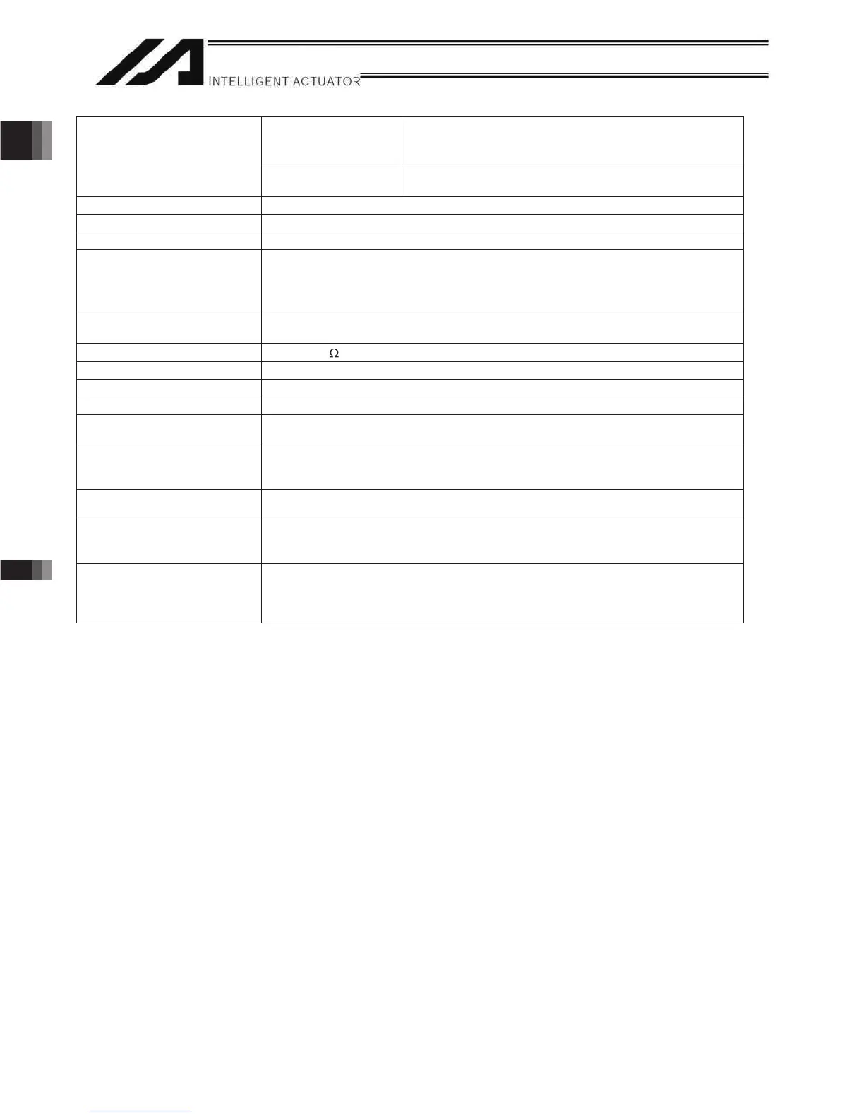
Controller with
expanded memory
(with gateway function)
128 programs
Number of programs
Controller without
expanded memory
64 programs
Multi-tasking 16 programs
Storage device Flash ROM + SRAM battery backup
Data input methods Teaching pendant or PC software
Absolute brake unit (brake-
type or absolute-specification
actuator only)
Built-in brake drive circuit
Driven by over-excitation at 90 V, released at 45 V (steady state)
No limitation on how many brake axes can be controlled (all 6 axes can be
equipped with brake).
Protective functions
Motor overcurrent, overload, motor-driver temperature check, overload check,
encoder-open detection
Regenerative resistance
Built-in (1 k , 20 W); expandable by external unit
Accessory I/O flat cable
Standard inputs 32 points or 16 points, NPN or PNP (set before shipment)
Standard outputs 16 points or 32 points, NPN or PNP (set before shipment)
RS232C port for teaching
serial interface
Enabled only in the manual operation mode.
IAI’s dedicated teaching pendant or ANSI teaching pendant (selected by a switch)
RS232C port for general PC
connection
Dedicated 2-channel RS232C, 9-pin DTE specification
Half-duplex at speeds up to 115.2 kbps (1 channel) or up to 76.8 kbps
(simultaneous communication with 2 channels)
Note 2)
Expanded inputs/outputs
(optional)
Expandable to 3 slots
Fieldbus interface (optional)
Profibus-DP (IN: 32 bytes max. / OUT: 32 bytes max.)
DeviceNet (IN: 32 bytes max. / OUT: 32 bytes max.)
CC-Link (IN: 32 bytes max. / OUT: 32 bytes max.)
Ethernet interface (optional)
Packet communication (client-server communication) by TCP/IP using SEL
language
XSEL PC software connection
MODBUS/TCP remote I/O (IN: 32 bytes max. / OUT: 32 bytes max.)
Note 1) The withstand voltage of the actuator motor is 1000 V for 1 minute.
Note 3) )RU52%2&\OLQGHU+LJK6SHHG7\SH5&6&7ƑFDOFXODWHZLWKWZLFHRIWKHPRWRUZDWWDJHGHVFULEHGRQWKHPRGHO
When performing a withstand voltage test with the controller and actuator connected, make sure the test voltage and duration
will not exceed 1000 V and 1 minute, respectively.
Note 2) If one RS232C channel is used at a communication speed of 115.2 kbps, use the other channel at 38.4 kbps or below. If these
speeds are exceeded, an overrun error or other problems will occur and successful communication cannot be guaranteed.
* RCS2-R**7/LS/LSA series actuators cannot be connected as axis 5 or 6.

 Loading...


