57
Part 1 Installation Chapter 6 Safety Circuit
Part 1 Installation
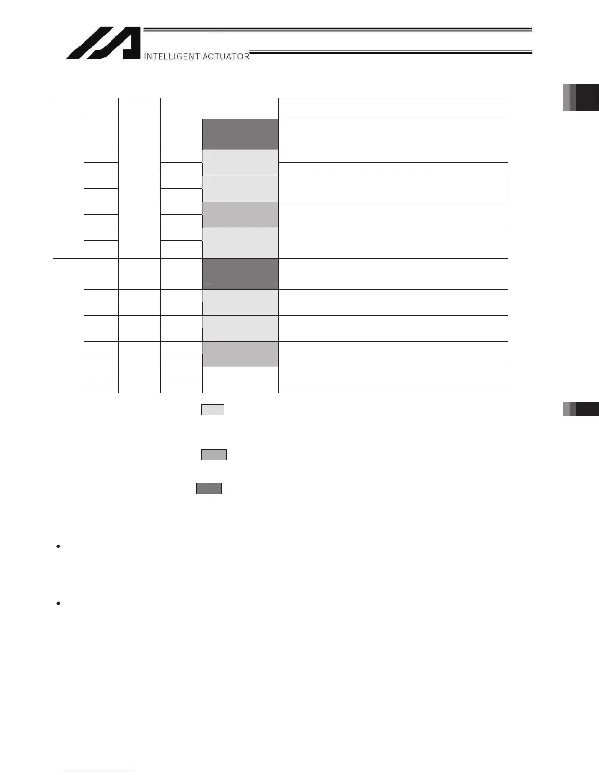
Terminal Assignments
Pin No.
Signal
name
sliateDweivrevO
9DET IN
To fused-contact
detection circuit
External contact error input (paired with No. 18)
Connected to the fused-contact detection contacts of the
safety circuit.
8 IN Emergency-stop detection input
7
EMGin
+24V
To EMG status of
safety circuit
24-V power output for emergency-stop detection input
6 line+
5
EMG1
line-
To EMG switch
circuit 1
Emergency-stop switch 1
Wire circuit 1 connected to EMG of the TP
4 line+
3
EMG2
line-
To EMG switch
circuit 2
Emergency-stop switch 2
Wire circuit 2 connected to EMG of the TP
2 Out+
Left
1
SDN
Out-
To interlock of
safety circuit
External relay drive source cutoff contact output
Signal for requesting the controller to cutoff the drive
source
18 DET +24V
To fused-contact
detection circuit
24-V power output for external contact error input
Connected to the fused-contact detection contacts of the
safety circuit.
17 IN Enable detection input
16
ENBin
+24V
To EMB status of
safety circuit
24-V power output for enable detection input
15 line+
14
ENB1
line-
To enable circuit
1
Enable switch 1 (safety gate, etc.)
Wire circuit 1 connected to ENB of the TP
13 line+
12
ENB2
line-
To enable circuit
2
Enable switch 2
Wire circuit 2 connected to ENB of the TP
11 Out+
Right
10
RDY
Out-
May be used if
necessary
Ready signal contact outputs (dry contacts) (for inductive
load of up to 200 mA)
In the table, the signals shown in fields (EMGin, EMG1, SDN, ENBin, ENB1) must always be connected
regardless of the required safety category. If these signals are connected wrongly or not connected, the safety
functions will be compromised.
In the table, the signals shown in fields (EMG2, ENB2) must be connected to meet safety category 3 or
above. They are designed to provide redundant safety circuits.
In the table, the signal shown in fields (DET) provides an input for detecting malfunction of the safety
circuit (mainly fused relay contacts). Be sure to use this signal if you want the XSEL controller to detect fused
contacts. If the safety circuit is configured as a closed system to manage fused contacts and other problems
independently, safety category 4 can be met without connecting this signal to the controller.
DET
DET (IN) and DET (+24V) are dry contact input terminals consisting of a photocoupler. By inputting fused-
contact detection signals from the drive-source cutoff safety circuit, the controller will be able to detect
problems in the external safety circuit.
SDN
SDN (OUT+) and SDN (OUT-) are output contacts that remain open while the controller is prohibiting the
motor power supply from the external power source. This condition will occur immediately after the controller
power is turned on, when an error occurs in the equipment, or when a drive-source cutoff cancellation
command is not received by the EMG or ENB line. Configure the circuit in such a way that the drive source
will never be turned on when these contacts are open.
When turning on the power, turn on the control power first, confirm that these contacts are closed, and then
turn on the drive power. (If the control power and drive power are turned on simultaneously, an “E6D, Drive-
source cutoff relay error” may generate.)

 Loading...


