v When you use memory mirroring, you must install a pair of DIMMs at a time.
One DIMM must be in channel 0, and the mirroring DIMM must be in the same
slot in channel 1. The two DIMMs in each pair must be identical in size, type,
and rank (single or dual), and organization, but not in speed. The channels run at
the speed of the slowest DIMM in any of the channels.
v Channel 2, DIMM connectors 7, 8, 9, 16, 17, and 18 are not used in
memory-mirroring mode.
v The maximum available memory is reduced to half of the installed memory when
memory mirroring is enabled. For example, if you install 64 GB of memory using
RDIMMs, only 32 GB of addressable memory is available when you use memory
mirroring.
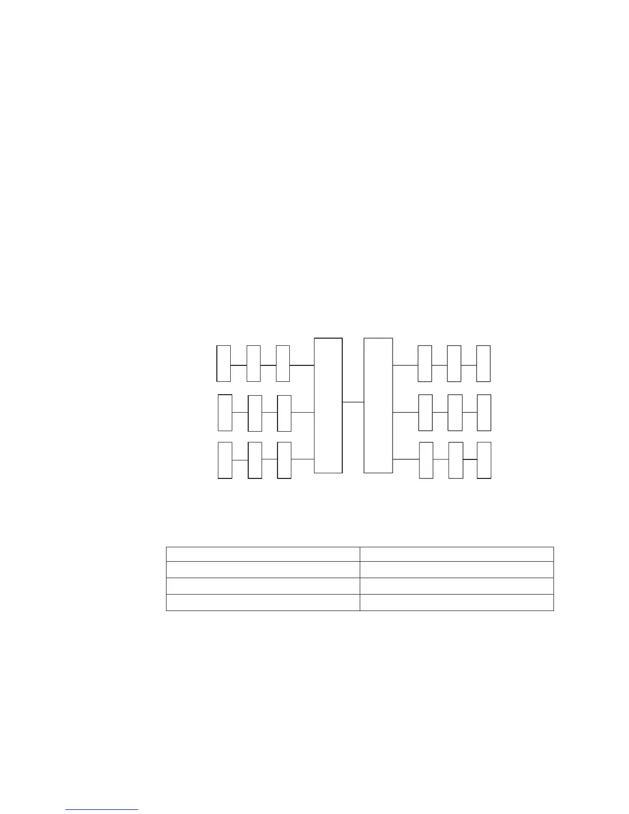
The following diagram shows the memory channel interface layout with the DIMM
installation sequence for mirroring mode. The numbers within the boxes indicate the
DIMM population sequence in pairs within the channels, and the numbers next to
the boxes indicate the DIMM connectors within the channels. For example, the
following illustration shows the first pair of DIMMs (indicated by ones (1) inside the
boxes) should be installed in DIMM connectors 1 on channel 0 and DIMM
connector 2 on channel 1. DIMM connectors 3, 6, 9, 12, 15, and 18 on channel 2
are not used in memory-mirroring mode.
The following table lists the DIMM connectors on each memory channel.
Table 15. Connectors on each memory channel
Memory channel DIMM connector
Channel 0 1, 2, 3, 10, 11, 12
Channel 1 4, 5, 6, 13, 14, 15
Channel 2 7, 8, 9, 16, 17, 18
The following illustration shows the memory connector layout that is associated with
each microprocessor. For example, DIMM connectors 10, 11, 12, 13, 14, 15, 16, 17,
and 18 (DIMM connectors are shown underneath the boxes) are associated with
microprocessor 2 (CPU2) and DIMM connectors 1, 2, 3, 4, 5, 6, 7, 8, and 9 are
associated with microprocessor 1 (CPU1). The numbers within the boxes indicate
the installation sequence of the DIMM pairs. For example, the first DIMM pair
(indicated within the boxes by ones (1)) should be installed in DIMM connectors 1
and 2, which is associated with microprocessor 1 (CPU1).
CH0
CH1
CH2
CPU1
1
1
2
2
3
3
3
6
21
5
4
8
7
CH2
CH0
CH1
4
4
6
12
10 11
15
16
1413
QPI
5
5
6
9
18
17
CPU2
Figure 1. Memory channel interface layout
198 IBM System x3550 M3 Types 4254 and 7944: Problem Determination and Service Guide

 Loading...


