5-10
Maintaining the CLARiTY Controller
Rev AA
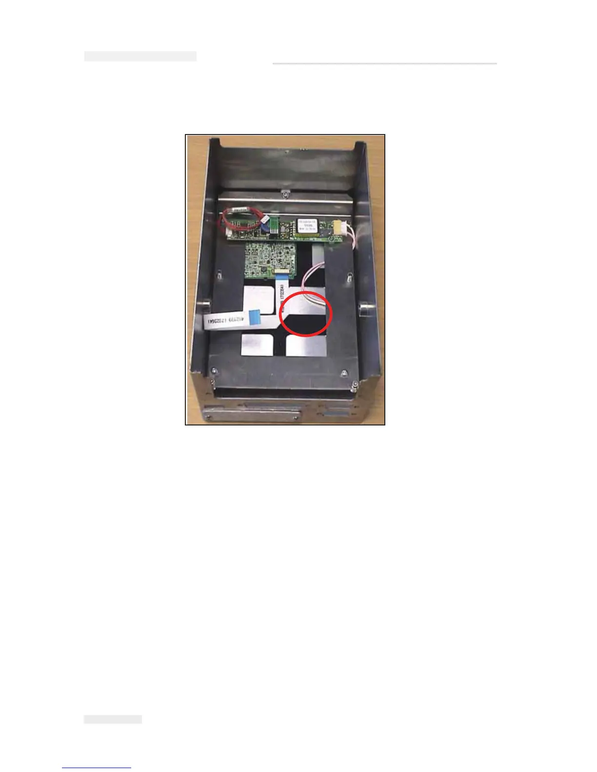
11 Replace the white ribbon cable ensuring that the right angle is as
shown (Figure 5-11).
12 Slide/lower this assembly back into the top case, being careful not to
damage the seal or to trap the backlight power cable and re-fit the
three securing screws and the anti-vibration washers.
13 Refit the Processor PCB with its two securing screws again taking care
not to trap the backlight power cable.
14 Refit the three connectors to the PCB and the securing screws for the
D-type connections.
15 Refit the power connector.
16 Replace the Top cover over the base and secure with the five screws
on the sides.
Figure 5-11: LCD Ribbon Cable Detail
IC
E Pegasus Service Manual