5-14
Maintaining the Printer
Rev AA
5 Disconnect the 8 electrical connectors located around the edge of the
PCB.
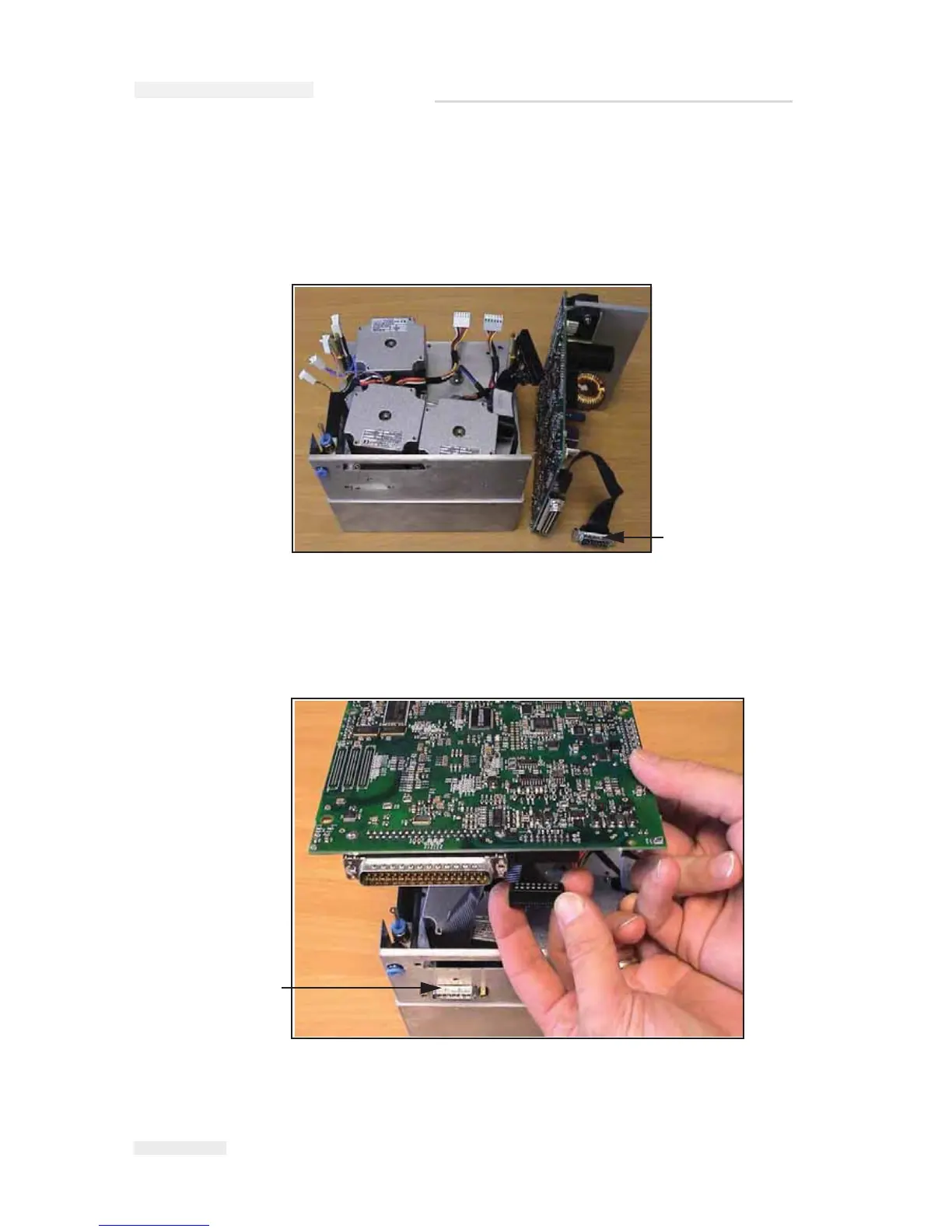
6 Undo the 2 screws securing the PCB to the supports and carefully
withdraw the PCB including the 15way D-Type connector for the I/O
connections (Figure 5-16).
7 Remove and retain the I/O connection ribbon cable.
8 To replace the PCB firstly insert and secure the I/O D-Type connector
to the side plate (Figure 5-17).
Figure 5-16: Main PCB Removed
I/O Connection
Cable
Figure 5-17: Main PCB Replacement
I/O D-Type Connector
I
CE Pegasus Service Manual