The band scope function allows you to visually check
signal condition around a specified frequency. The IC-
746’s band scope function can be used not only in FM
mode but also when operating on HF bands.
The band scope measures receive signal conditions
over a specified range on either side of a selected fre-
quency in either VFO or memory modes.
➀ While menu set 1 is displayed, push [F5](SCP) to
select the band scope menu.
➁ Rotate the tuning dial to select a frequency.
➂ Push [F5](STEP) one or more times to select a
sweep step.
• During sweep operation “”appears and received
signals cannot be heard.
• If there is a lot of signal noise, turn the preamp OFF and
the attenuator ON to reduce the signal input level and im-
prove the readability of the band scope.
➃ When rotating the tuning dial and finding a signal
you wish to communicate on, simple communicate
normally.
• If you want to return to the previous frequency (before ro-
tating the tuning dial), push [F3] for 2 sec.
➄ While receiving, if you want to update the band con-
ditions using the selected sweep step, push [F1].
• Each push of [F1] starts and stops the sweep function.
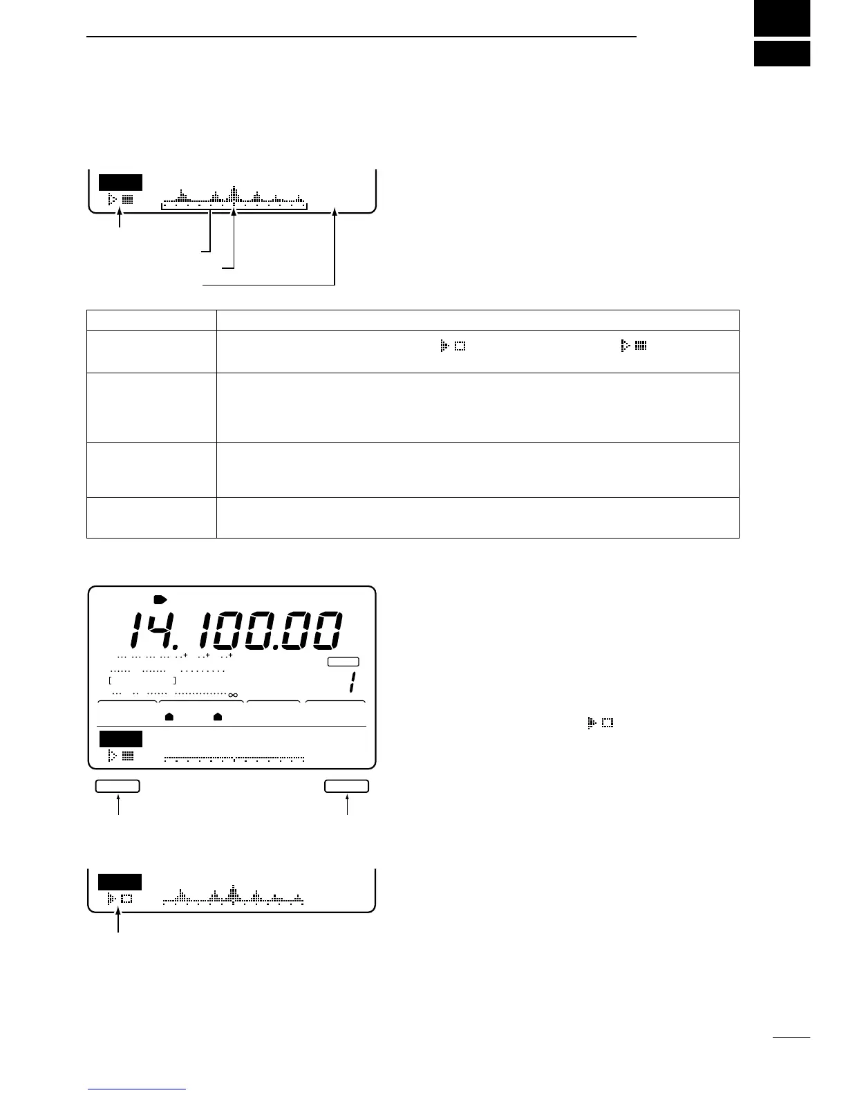
INDICATOR
SWEEP
BAND SCOPE
INDICATOR
FREQUENCY
INDICATOR MARK
SWEEP STEP
DESCRIPTION
While the band scope is “sweeping,”“ ”appears; while stopped “”appears. Re-
ceived audio is not emitted from the speaker while the band scope is “sweeping.”
Indicates the relative strength of signals and their location in relation to the center fre-
quency. Signal strength is relative to the S-meter level, S1 to S9, with each vertical dot in
the band scope indicator equal to one segment of the S-meter. Signal activity is measured
±30 steps from the center frequency with each step equal to the selected sweep step.
After a sweep, indicates the relative position of the selected frequency.When the selected
frequency is outside of the sweep range, this indicator flashes. After changing the fre-
quency, push [F3] to automatically return to the center frequency.
Indicates the selected sweep step. 0.5, 1, 2, 5, 10, 20 and 25 kHz are selectable. Each dot
of the band scope indication is approx. equal to the selected sweep step.

 Loading...


