EasyManuals Logo

Icom IC-746 Instruction Manual

Icom IC-746
90 pages
To Next Page IconTo Next Page
To Previous Page IconTo Previous Page
Page #78 background imageLoading...
Page #78 background image
76
13
OPTIONAL INSTALLATIONS
13-1 Opening the transceivers
case
Follow the case and cover opening procedures shown
here when you want to install an optional unit or adjust
an internal unit, etc.
v CAUTION: DISCONNECT the DC power cable
from the transceiver before performing any work on
the transceiver. Otherwise, there is danger of elec-
tric shock and/or equipment damage.
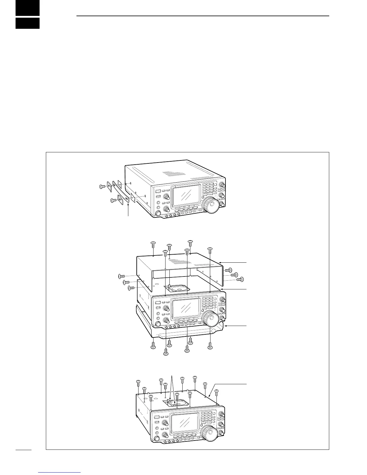
Carrying handle
Top cover
Bottom cover
Shield cover
Shield cover
Speaker screws
Remove the 2 screws from the left side of the trans-
ceiver to remove the carrying handle.
Remove 6 screws from the top of the transceiver
and 6 screws from the sides, then lift up the top
cover.
Remove the 11 screws from the shield cover and
the 2 screws from the speaker.
Remove the 6 screws from the bottom of the trans-
ceiver, then remove the bottom cover.

Table of Contents

Other manuals for Icom IC-746

Questions and Answers:

Question and Answer IconNeed help?

Do you have a question about the Icom IC-746 and is the answer not in the manual?

Icom IC-746 Specifications

General IconGeneral
ModeSSB, CW, RTTY, AM, FM
Receiver TypeDouble conversion superheterodyne
Antenna ConnectorSO-239
Voltage13.8 V DC ±15%
Impedance50 ohms
Output Power100 W (SSB, CW, FM, RTTY), 40 W (AM)
Current DrainTX: 20 A
SensitivityAM: 2 µV
SelectivityCW: 500 Hz (-6 dB)

Related product manuals