77
13
OPTIONAL INSTALLATIONS
13-3
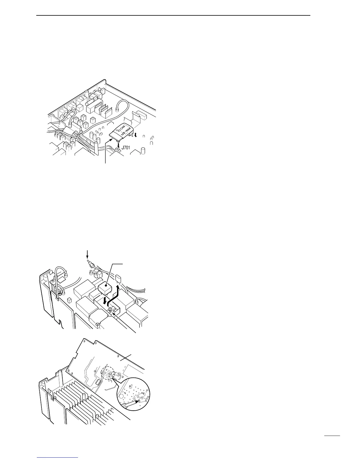
CR-282
HIGH STABILITY
CRYSTAL UNIT
By installing the CR-282, the total frequency stability
of the the transceiver will be improved.
➀ Remove the bottom cover as shown on the page op-
posite.
➁ Turn the transceiver upside down. Remove 8 screws
from the PLL UNIT, disconnect J121 and J151, then
remove the PLL UNIT.
➂ Remove the supplied internal crystal and replace
with the CR-282.
➃ Adjust the reference frequency using a frequency
counter.
➄ Return the PLL UNIT and bottom cover to their orig-
inal positions.
Connect a frequency counter here
and adjust the frequency to 60.00000 MHz.
J
262
J
151
J
121
Internal crystal
PLL UNIT
CR-
282
L
1901
2
LO IN
The UT-102 announces the accessed readout’s fre-
quency, mode, etc. (S-meter level can also be an-
nounced—p. 63) in a clear, electronically-generated
voice, in English (or Japanese).
➀ Remove the bottom and shield covers.
➁ Remove the protective paper attached to the bottom
of the UT-102 to expose the adhesive strip.
➂ Plug UT-102 into J701 on the MAIN UNIT as shown
at left.
➃ Return the top and shield covers to their original po-
sitions.
13-2
UT-102
VOICE SYNTHESIZER UNIT