42
5
FUNCTIONS FOR RECEIVE
5-11 Selecting IF filters
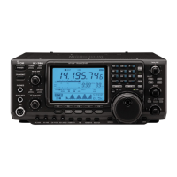
Optional filters can be installed in the IF stage of the
IC-746 (p. 78). Both 9 MHz and 455 kHz IF filters are
available. When an optional filter is installed, set the
optional filter setting using filter program mode (see
below). Filters can be independently selected for each
operating mode.
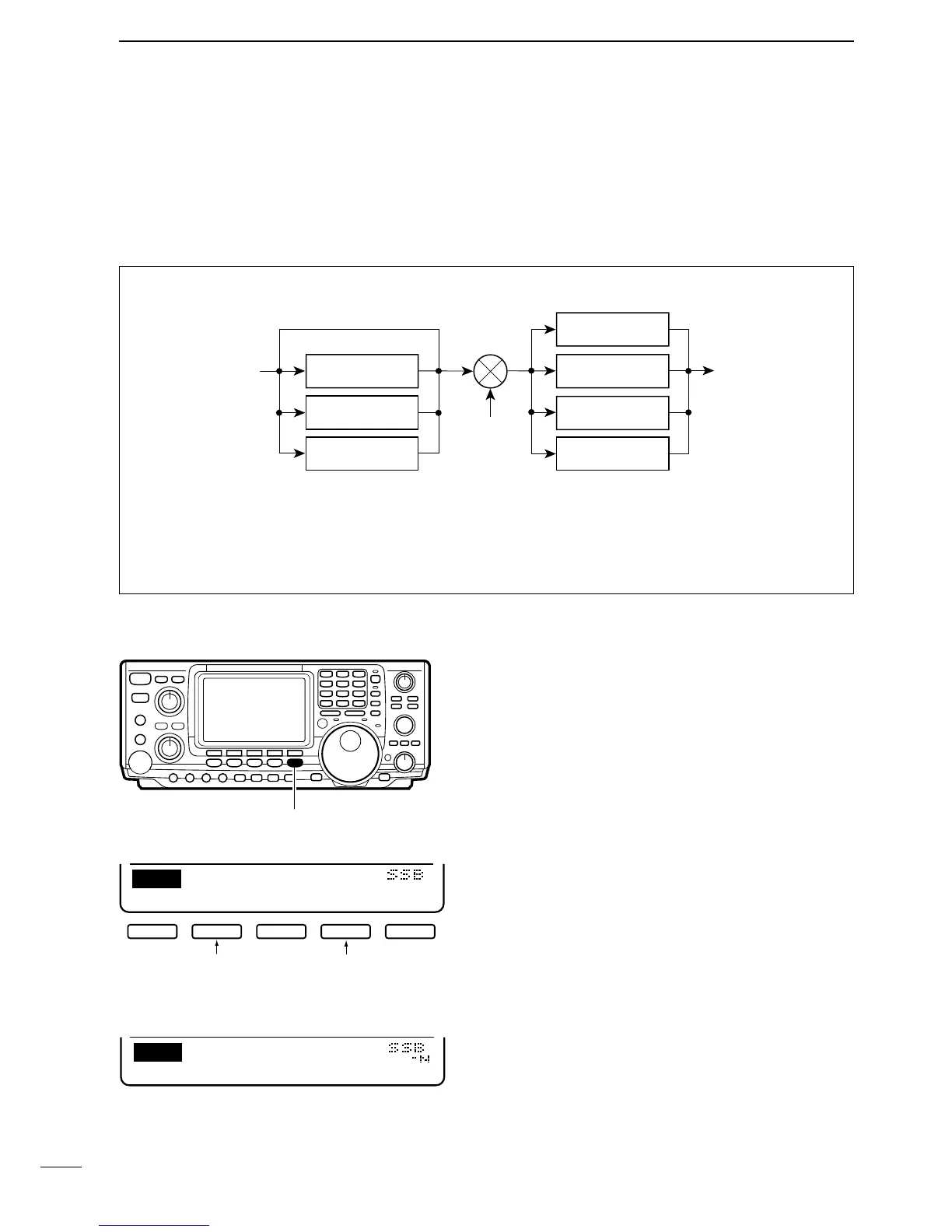
FILTER CONSTRUCTION
☞ NOTE: one 455 kHz
optional filter can be
installed; two 9 MHz
optional filters can be
installed.
■ FILTER PROGRAM MODE SETTINGS ➀ Push [FILTER] for 2 sec. to select filter program
mode.
➁ Push a mode key to select an operating mode for
the filter setting.
➂ Push [FILTER] to set the filter condition to normal or
narrow.
•“NAR” appears when narrow is selected.
➃ Push [F2](9M) or [F4](455k) one or more times to
select a 9 MHz filter or a 455 kHz filter, respectively.
➄ Repeat steps ➁ to ➃ to set filters for other operat-
ing modes, if desired.
➅ Push [MENU] to return to regular operation.
☞ NOTE: See p. 78 for activating the installed optional
filter(s).


 To Next Page