EasyManua.ls Logo

Icom IC-746 - Section 9: Board Layouts (Continued); Phone Board Bottom View Layout; Display Board Bottom View Layout; PBT and RIT Board Layouts (Continued)

Icom IC-746
90 pages
Print Icon
To Next Page IconTo Next Page
To Previous Page IconTo Previous Page
Loading...
47
6
FUNCTIONS FOR TRANSMIT
6-6 Split frequency operation
Lights during split operation
[SPLIT]
Tuning dial[XFC]
BLANK
CH
VFOA
ANT
AGCAMP
P.
SWR
ALC
Po
S
20 50
3211.5
579 20 40 60
100%
1
1
S
14.10000
LSB
LSB
M1
AGCDUPCMPTCNSCP
SPLIT
BLANK
CH
ANT
AGCAMP
P.
SWR
ALC
Po
S
20 50
3211.5
579
100%
1
1
S
7.06200
M1
AGCDUPCMPTCNSCP
SPLIT
USB
BLANK
CH
ANT
AGCAMP
P.
SWR
ALC
Po
S
20 50
3211.5
579
100%
1
1
S
7.06200
M1
AGCDUPCMPTCNSCP
SPLIT
VFOB
VFOB
Push [SPLIT] to show VFO B contents
13
13
13
20 40 60
20 40 60
Operation to step
Selecting VFO B
Operation to step
Split frequency operation allows you to transmit and re-
ceive in the same mode on two different frequencies,
one in VFO A, the other in VFO B.
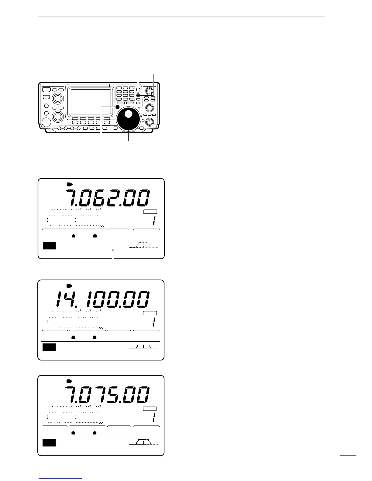
[EXAMPLE]: Operating split with VFO A set to receive
7.06200 MHz/LSB; VFO B set to transmit 7.07500
MHz/LSB.
Set VFO A to 7.06200 MHz/LSB mode.
Push [SPLIT] to turn split frequency operation ON.
•“SPLIT appears and the [SPLIT] indicator lights.
When split frequency operation is ON the function dis-
play indicates the transmit frequency.
Set VFO B to 7.07500 MHz/LSB.
While VFO A is displayed, push and hold [XFC],
then rotate the tuning dial to set the frequency.
While pushing [XFC], the operating band and mode
can be changed, if desired.
While pushing [XFC], the transmit frequency is moni-
tored.
NOTE: Cross band split operation may also be pos-
sible but is not guaranteed.

Table of Contents