79
13
OPTIONAL INSTALLATIONS
CONNECTING A NON-ICOM LINEAR AMPLIFIER
v WARNING:
Set the transceiver output power and linear ampli-
fier ALC output level referring to the linear amplifier
instruction manual.
The ALC input level must be in the range 0 V to –4
V, and the transceiver does not accept positive
voltage. Non-matched ALC and RF power settings
could cause a fire or ruin the linear amplifier.
☞ NOTE: The specifications for the SEND relay are
16 V DC/2 A. If this level is exceeded, a large ex-
ternal relay must be used.
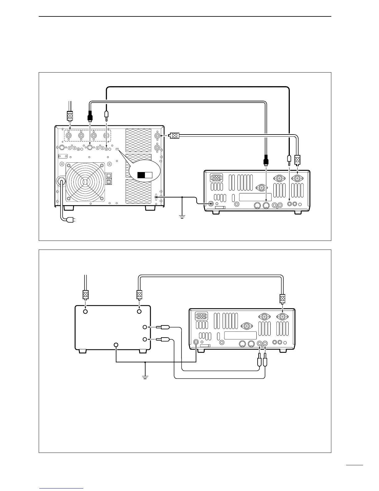
CONNECTING THE IC-PW1
NOTE: Turn OFF the transceiver’s antenna tuner while tuning the IC-PW1’s tuner.
13-5
Linear amplifier connections
To antenna
ANT
ACC(1)
ACC cable (supplied with the IC-PW1)
Mini-plug cable (supplied with the IC-PW1)
Coaxial cable
(supplied with the IC-PW1)
ACC(2)
ANT
1
REMOTE
REMOTE
INPUT
1
GND
GND
ground
IC-PW1
IC-746
to AC outlet
EXCITER
12

 Loading...


