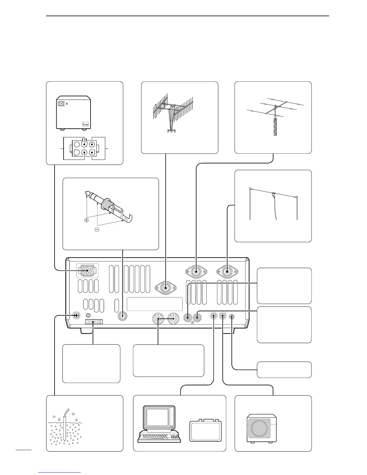
DC POWER SUPPLY (p. 69)
ELECTRONIC KEYER
TUNER
(p. 80)
Accepts the control
cable from the optional
AH-4
HF AUTOMATIC
ANTENNA TUNER.
ACC SOCKETS 1/2 (p. 72)
Enables connection to ext.
equipment such as a TNC
for data communications.
ALC JACK (p. 79)
COMP GAIN (p. 40)
CONTROL
SEND JACK
(p. 79)
REMOTE JACK (p. 74)
GROUND (p. 70)
EXTERNAL SPEAKER
JACK
144 MHz ANTENNA
(p. 70)
HF/50 MHz ANTENNA (p. 70)
[ANT2]
[ANT1]
PS-85
(optional)
HF/50 MHz ANTENNA
(p. 70)
SP-20
(optional)
Impedance: 4–8 Ω
Input for external remote control signals.
Connect this
terminal to a
ground to
prevent electrical
shocks, TVI, BCI
and other
problems.
Connect a VHF (60–144 MHz)
antenna; impedance: 50 Ω.
Connect an HF/50 MHz
antenna; impedance: 50 Ω.
Connect an HF/50 MHz
antenna; impedance: 50 Ω.
Accepts a paddle to activate the internal
electronic keyer.
Connects to the ALC
output jack of a non-
Icom linear amplifier.
ALC input: 0–4 V.
Goes to ground when
transmitting for exter-
nal equipment such
as a linear amplifier.
CT-
17
+
_


 To Next Page