7
1
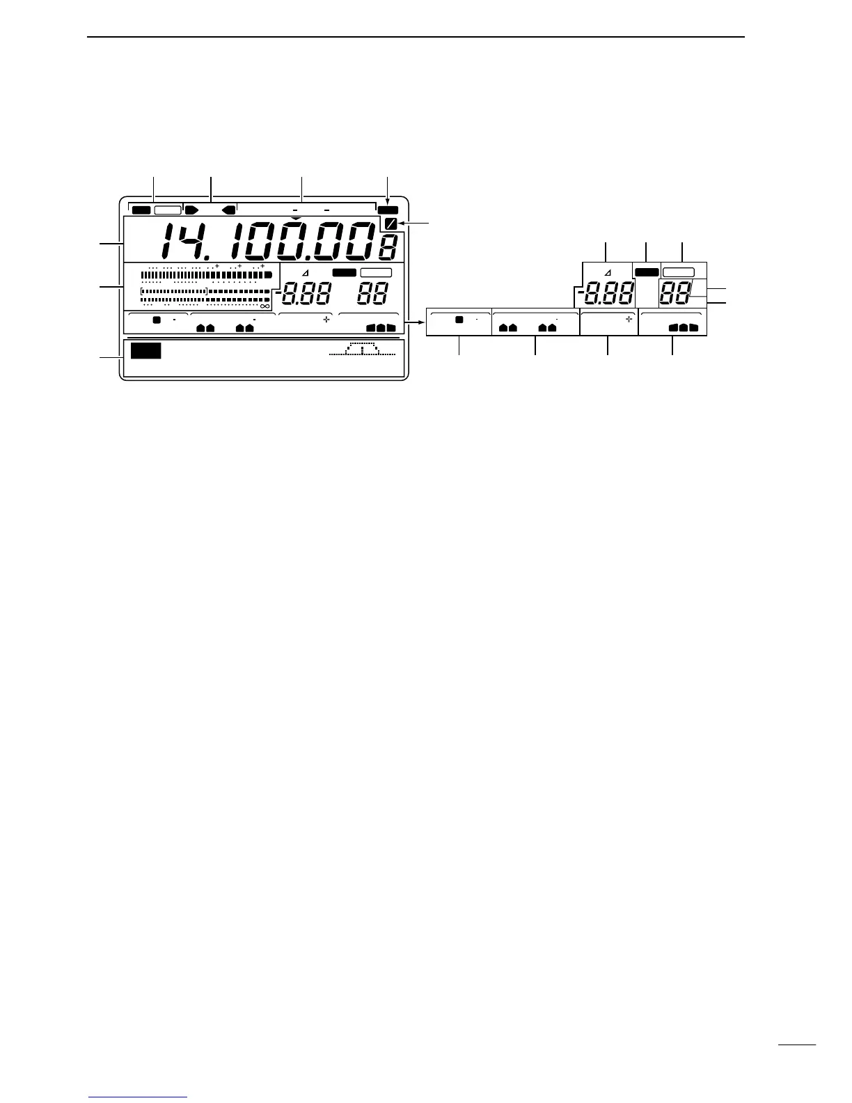
PANEL DESCRIPTION
q ANTENNA TUNER INDICATORS (pgs. 59, 79)
➥ “TUNE” appears when the antenna tuner is ON;
“TUNE” appears and flashes during manual tun-
ing.
➥ “EXT” appears when the optional AH-4 external
HF antenna tuner is connected to [ANT1].
w ANTENNA INDICATORS (p. 71)
Indicate which antenna connector is in use for
HF/50 MHz.
e MODE INDICATORS (p. 7)
Indicate the selected operating mode.
r NARROW FILTER INDICATOR (p. 42)
Appears when the narrow IF filter is selected.
t
1
⁄4 TUNING DIAL SPEED INDICATOR (p. 39)
Appears when the tuning dial is set so that one rev-
olution is equal to
1
⁄4 of the normal revolution.
y FREQUENCY READOUT
Shows the operating frequency.
u MULTI-FUNCTION METER INDICATION
Displays S-meter reading during receive; “P
0,”“ALC”
and “SWR” meters can be selected for transmit.
i RIT/
:TX INDICATORS (pgs. 38, 45)
Appear during RIT or :TX operation and indicate
the frequency offset.
o VFO/CALL/MEMORY INDICATORS
Indicate whether VFO A, VFO B, the call channel or
memory mode is selected.
!0 BLANK MEMORY INDICATOR (p. 49)
Appears when the selected memory channel is
blank.
!1 SELECT MEMORY INDICATOR (p. 57)
Appears when the selected memory channel is a
“select” memory channel.
!2 MEMORY CHANNEL INDICATOR (p. 49)
Shows the selected memory channel.
!3 TRANSMIT FUNCTION INDICATORS
Indicate functions selected for transmit.
!4 RECEIVE FUNCTION INDICATORS
Indicate functions selected for receive.
!5 SPLIT FUNCTION INDICATOR
Appears during split operation.
!6 DSP FUNCTION INDICATORS
Appear when DSP functions are selected.
!7 MULTI-FUNCTION SWITCH INDICATORS (p. 8)
Indicate the functions assigned to the multi-function
switches (F1–F5).
1-3 Function display

 Loading...


