© 2009 IDS Imaging Development Systems GmbH 197
9 Specifications
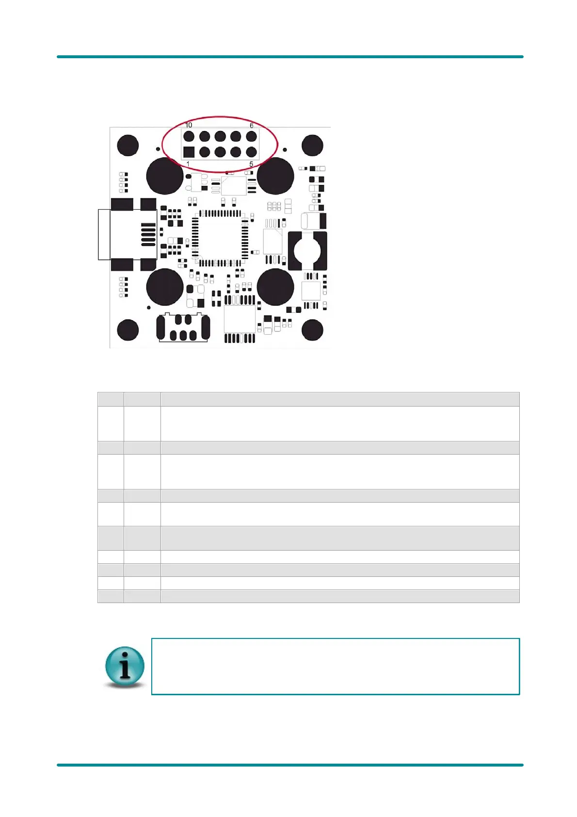
Pin Assignment of the I/O Connector
Figure 182: USB uEye LE - Pin assignment of the I/O
connector (board-level version only)
USB power supply (VCC) 5 V
Max. admissible current = 500 mA
Current consumption of the LE camera itself: 300...350 mA.
Power supply of the internal voltage transformer
Supply voltage 3.3 V or 3.0 V
*1)
Max. admissible current 230 mA (3.3 V) or 250 mA (3.0 V)
Programmable input/output (General Purpose I/O) 1
I2C bus clock signal
Supply voltage 3.3 V or 3.0 V
*1)
I2C bus data signal
Supply voltage 3.3 V or 3.0 V
*1)
Programmable input/output (General Purpose I/O) 2
*1) This voltage depends on the supply voltage required for the sensor used (see table below)
The I/O connector of the uEye LE can be provided with a 2 x 5-pin connecting plug with a
2.54 mm (0.1") lead spacing.
IDS shall not be liable for any damage to the camera or connected devices arising from
installation of the connecting plug.
 Loading...