6 Chapter 1 Product Overview
Ehave Series Full Digital IGBT CO
2
/MAG/MMA Multifunctional Inverter Welder User Manual
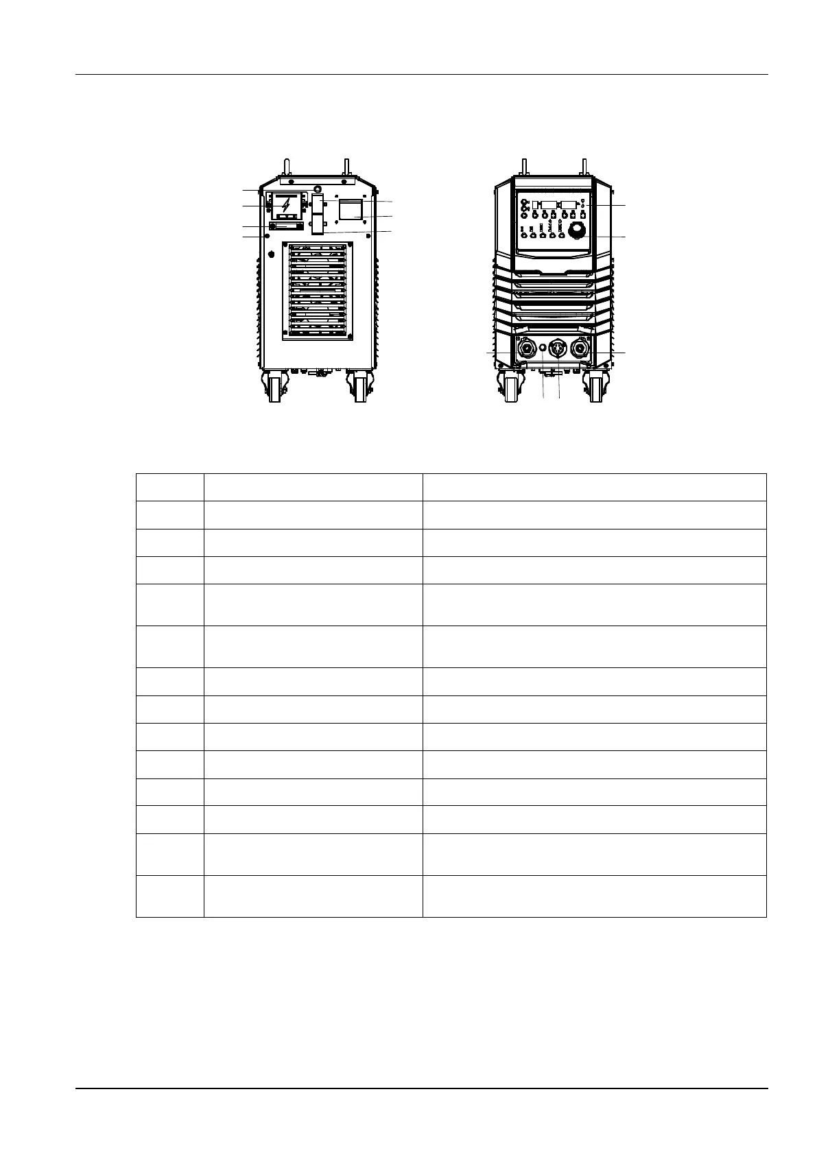
Figure 1-4 shows the structure of the welder.
Figure 1-4 Welder structure
Connects to the AC power supply.
Fastens the AC power input cable.
Connects to the grounding cable.
Fuse holder of the electrically-heated
gas regulator
Provide an 8 A fuse tube capacity.
Socket of the electrically-heated gas
regulator
Provides a 36 V AC power supply for the electrically-heated
gas regulator.
Facilitates communication with a computer.
Connects or disconnects the AC power supply.
Connects to the welding material power cable.
Connects to the wire feeder power cable.
Connects to the wire feeder control cable.
Fuse holder of the wire feeder
Provide an 8 A fuse tube capacity.
Parameter adjustment knob
Adjusts welding parameters. For details, see the operation
description.
Adjusts the welding mode. For details, see the operation
description.
1.4.2 Configuration
Table 1-3, Table 1-4, and Table 1-5 show the configuration lists of welders.