16 Chapter 2 Installation and Cabling
Ehave Series Full Digital IGBT CO
2
/MAG/MMA Multifunctional Inverter Welder User Manual
3. Remove 20 mm of the insulation layer from both ends of the power cable, insert the cable
into the rearend sleeves of the bare crimp terminals, use the crimping pliers to tighten the
sleeves, and use heat shrink tubing to insulate the bare crimp terminals.
4. Use a screw driver to remove the protective cover of the aviation plug, remove 5 mm of the
insulation layer of the 7 cores, use a soldering iron to connect the 7 cores of the control
cable to the 7 pins of the aviation plug, use heat shrink tubing to insulate the bare parts,
install the protective sleeves of the 7-core control cable, and restore the protective cover of
the aviation plug.
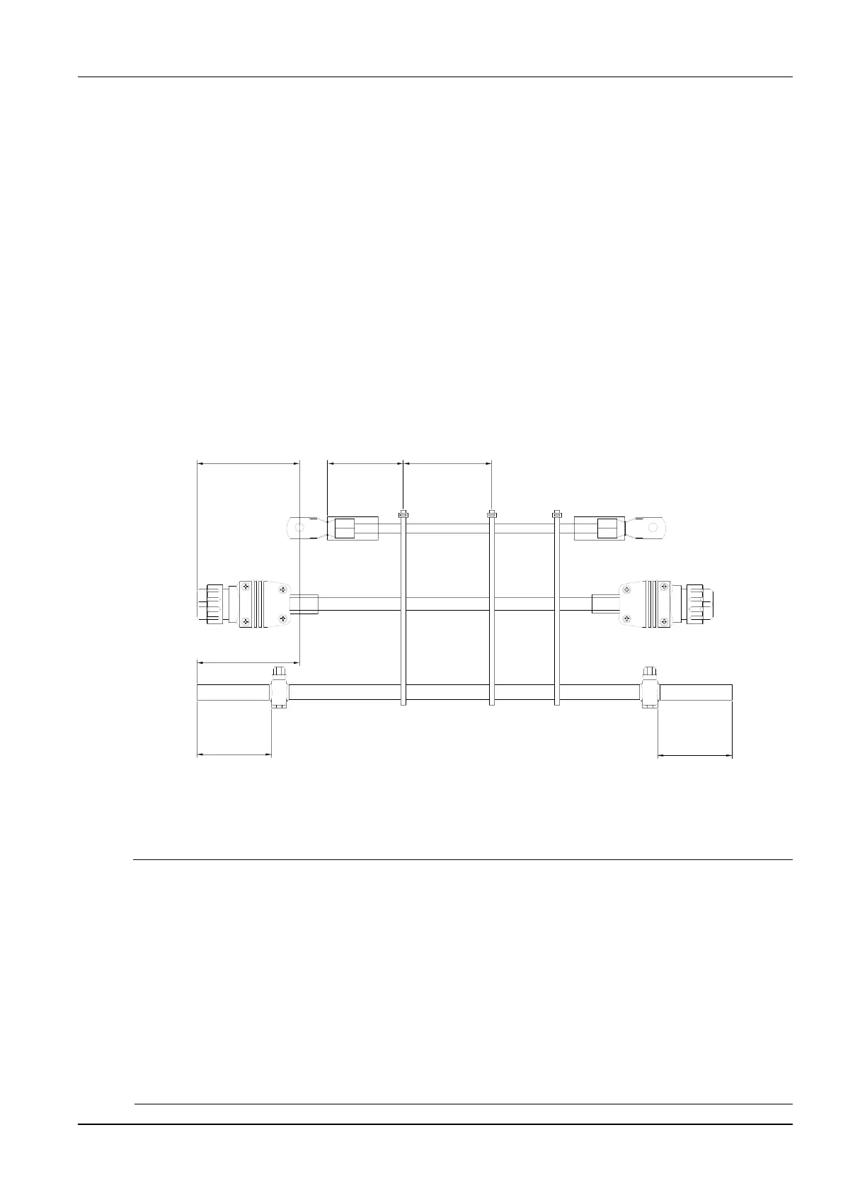
5. Insert the gas tube through the two hose clamps and use a screw driver to fix each of them
at100 mm away from each end of the tube.
6. Use cable ties to tie the cables and tube together at every 600 mm. At the end connected to
the wire feeder, the 7-core control cable must be 110 mm longer than the power cable and
the gas tube must be 110 mm longer than the power cable. At the end connected to the
welder, the excessive lengths of the control cable and gas tube are not handled. Figure 2-2
shows the way to tie the cables and tube.
600 mm 600 mm110 mm
110 mm
100 mm
100 mm
Power cable
Protective
sleeve
Cable tie
Gas tube
End connected to the wire feeder
Clamp
7-core aviation plug
Bare crimp terminal
Connected to the welder power supply
7-core control
cable
Figure 2-2 Schematic diagram of tying cables and tube
2.6 Electric Connections
Safety Warning
1. Connections must be set up by certified professional electric device operators.
2. Electric connections can be set up only after the distribution box is switched off and necessary safety
measures are taken.
3. Use specified cables.
4. Do not touch electric connections with wet hands.
5. Do not place heavy objects on the power cables.
6. Running water pipes and reinforcing bars of houses may not be adequately grounded. Do not
connect grounding cables to them.
7. Each welder is equipped with one air circuit breaker or fused switch.