34 Chapter 3 Welder Operation Description
Ehave Series Full Digital IGBT CO
2
/MAG/MMA Multifunctional Inverter Welder User Manual
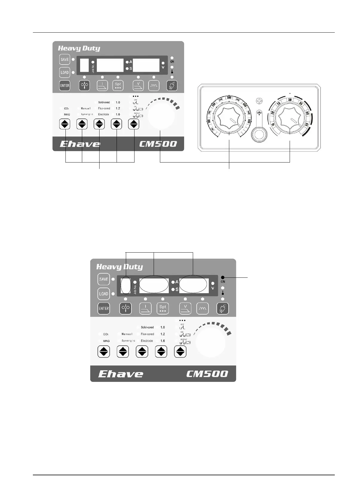
Knobs
Buttons
Current
(
A
)
Adjust
current
Manual/Syn
ergic tuning
Inch wire
Voltage
(
V
)
Standard
Figure 3-3 Positions of buttons and knobs
3.3 Screens and LED Indicators
Figure 3-4 shows the screens and LED indicators.
Figure 3-4 Positions of screens and LED indicators
The left screen displays the numbers of saved or loaded channels and the locking state. When
the saving or loading function is used, the Job No. indicator turns on and the left screen
displays the number of the active channel which ranges from 0 to 9. When the locking function
is used, the left screen displays L, indicating common locking and password change.
Meanwhile, the Job No. indicator flashes, indicating parameter value range locking.
The middle screen displays a current value, a spot welding time, or a code. When the current
indicator A turns on, it displays a current value. When the spot welding time indicator S turns