Chapter 2 Installation and Cabling 25
Ehave Series Full Digital IGBT CO
2
/MAG/MMA Multifunctional Inverter Welder User Manual
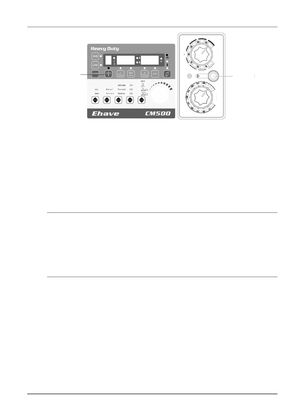
Voltage
(
V
)
Standard
Manual/Synergic
tuning
Inch wire
Wire inching
button
Current
(A
)
Adjust current
Figure 2-12 Position of the wire inching button
Usage Notes
1. The wire inching roll must match the wire diameter and selection of the wire inching roll does
not depend on the welding wire type.
2. Use the wire inching pressure lever to adjust the pressure of the wire inching roll according
to the wire diameter. For details, see the wire feeder user manual.
3. If you use a flux-cored wire, use the lever to reduce the pressure to slightly lower than that
for a solid wire.
Safety Warning
1. Do not check at a short distance whether the wire has been extended through the tip; otherwise, the
wire may injure your eyes or skin.
2. When you use a welding torch with a resin wire inching tube to manually inch wire, stretch the power
cable of the welding torch and set the wire inching speed (current) to less than half of the rated value,
so as to prevent the wire from piercing the wire inching tube and welding torch power cable in case
that the welding torch power cable is excessively bent.
3. Upon finding a crack in the welding torch power cable or wire inching tube, replace the damaged
cable or tube.
2.7.6 Welding Conditions
Under the standard welding conditions, the welding parameters in the following tables are
applicable, including the common parameters for CO
2
welding (solid wire), MAG welding (solid
wire; Ar 80% + CO
2
20%), and flux-cored wire. In actual welding projects, modify the
parameters according to the workpiece materials, workpiece shapes, and welding positions. If
high welding quality is required, you are recommended to determine the optimal welding
process parameters through tests. The wire diameter adopted for the actual welder shall
prevail.