Chapter 2 Installation and Cabling 15
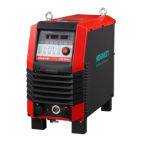
Ehave Series Full Digital IGBT CO
2
/MAG/MMA Multifunctional Inverter Welder User Manual
Table 2-3 Packing list for the cable bundle component box of Ehave CM250/350/350AR
Both ends of the power
cable
Both ends of the power
cable
Both ends of the control
cable
Protective sleeve for
the 7-core cable
Both ends of the control
cable
Both ends of the gas
tube
Ring-shaped
non-insulated terminal
Cable bundle preparation manual for Ehave
series welders
Table 2-4 Packing list for the cable bundle component box of Ehave CM500/500H/500AR
Both ends of the power
cable
Both ends of the power
cable
Both ends of the control
cable
Protective sleeve for
the 7-core cable
Both ends of the control
cable
Both ends of the gas
tube
Ring-shaped
non-insulated terminal
Cable bundle preparation manual for Ehave
series welders
2.5.2 Cable Bundle Preparation Description
1. The cable bundle consists of the power cable, 7-core control cable, and gas tube. When
preparing the cable bundle, make sure that the 7-core control cable is 0.3 m longer than the
power cable and the gas tube is 1.5 m longer than the power cable.
2. The cross-sectional area of the power cable depends on the length. For Ehave
CM250/350/350AR, if the power cable length ranges from 0 m to 15 m (included), the
default cross-sectional area is 35 mm
2
, while if the power cable length ranges from 15 m to
30 m, the default cross-sectional area is 50 mm
2
. For Ehave CM500/500H/500AR, if the
power cable length ranges from 0 m to 30 m (included), the default cross-sectional area is
50 mm
2
, while if the power cable length ranges from 30 m to 50 m, the default
cross-sectional area is 70 mm
2
. Use the bare crimp terminals matching the cable.