Chapter 2 Installation and Cabling 19
Ehave Series Full Digital IGBT CO
2
/MAG/MMA Multifunctional Inverter Welder User Manual
3. If CO
2
is used as the shielding gas, connect the heating power cable to the 36 V AC power
jack of regulator on the rear of the welder.
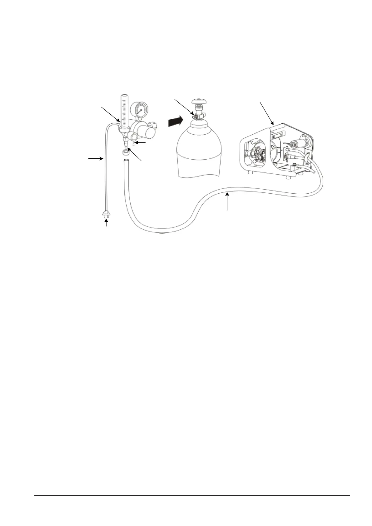
4. Connect the grounding cable to implement reliable grounding. Figure 2-6 shows the cable
connections.
Regulator
Gas outlet
Wire feeder
Regulator
Grounding
cable
Regulator
Gas tube
connector
Gas tube
36 V power plug
Regulator
power cable
for heating
Figure 2-6 Schematic diagram of connecting the gas tube
Gas Usage Notes
1. If the welder works in the CO
2
welding mode, use CO
2
as the shielding gas.
2. If the welder works in the MAG welding mode, use the mixed gas, which consists of CO
2
(5% - 10%) and Ar (purity > 99.9%), as the shielding gas.
3. If two types of gas must be mixed, use a gas mixer and ensure that the gases are mixed
evenly.
2.6.3 Connecting the Wire Feeder
The procedure for connecting the wire feeder is as follows:
1. Fix the 7-core control cable, gas tube, and positive output welding cable with the clamp at
the rear of the wire feeder. See Figure 2-7.