20 Chapter 2 Installation and Cabling
Ehave Series Full Digital IGBT CO
2
/MAG/MMA Multifunctional Inverter Welder User Manual
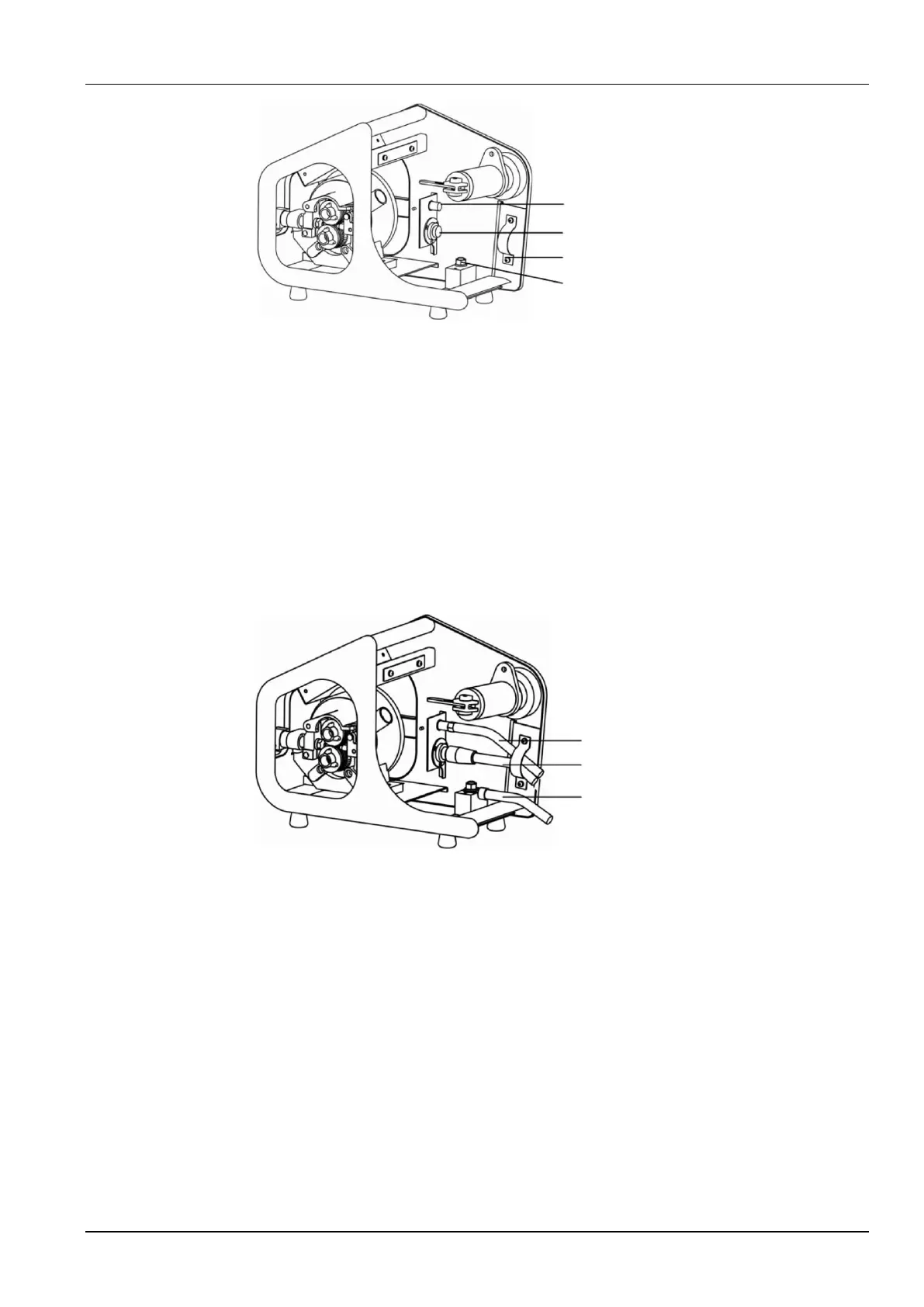
Gas tube connector
7-core aviation jack
Clamp
Nut for fixing a
welding cable
Figure 2-7 Schematic diagram of connecting the wire feeder
2. Connect the 7-core aviation plug of the control cable to the 7-core aviation jack on the fixing
plate of the wire feeder, and fix the cable.
3. Connect the gas tube to the copper connector on the fixing plate of the wire feeder and
fasten the hose clamp of the gas tube.
4. Connect the positive output welding cable to the threaded rod on the bottom plate of the wire
feeder, and use a adjustable wrench to fasten the nut.
5. Figure 2-8 shows the cable connections.
Gas tube
7-core control cable
Output welding cable
Figure 2-8 Schematic diagram of connecting the wire feeder
2.6.4 Connecting the Welding Torch
After cabling for the wire feeder is complete, refer to the wire feeder user manual and welding
torch user manual to connect the welding torch to the wire feeder. Figure 2-9 shows the
connection.