Chapter 3 Welder Operation Description 31
Ehave Series Full Digital IGBT CO
2
/MAG/MMA Multifunctional Inverter Welder User Manual
Chapter 3 Welder Operation Description
3.1 Welder Control Panel Structure
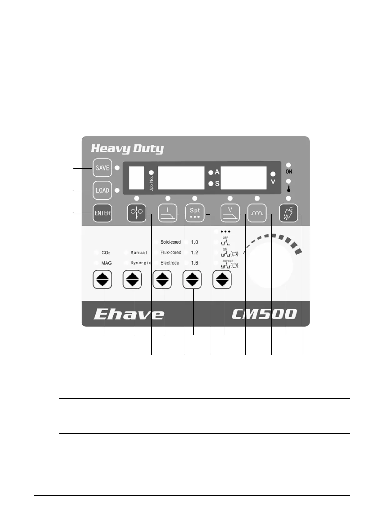
3.1.1 Front Control Panel
Figure 3-1 shows the front control panel of the welder and the buttons on the control panel.
1
2
3
4 5
6 7
8 9
10
11
12 13 14
15
Figure 3-1 Front control panel
Note
The preceding figure shows the front control panel of Ehave CM500, which is the same as those of
Ehave CM500H/500AR. On the front control panels of Ehave CM250/350/350AR, the wire diameters are
0.8, 1.0, and 1.2.