66 Chapter 4 Maintenance
Ehave Series Full Digital IGBT CO
2
/MAG/MMA Multifunctional Inverter Welder User Manual
The procedure is as follows:
1. Turn off the distribution box power supply.
2. Disconnect all the grounding cables of the housing.
3. Remove all peripherals including the wire feeder from the welder.
4. Connect the three input terminals of the input busbar to create a short circuit.
5. Turn the switch of the welder to the ON position.
6. Connect the positive output terminal, negative output terminal, and pin 7 of 7-core aviation
plug using cables to create a short circuit.
7. Connect pins 1 - 6 of the 7-core aviation plug and pins 3 and 8 of the communication
connector using cables to create a short circuit.
8. The models of the cables used to create short circuits must be the same and the cross-sectional
area of each cable must not be smaller than 1.25 mm
2
.
Note
All changes and alteration performed for the voltage resistance test must be removed after the test.
4.3 Troubleshooting
4.3.1 Welder Fault Indicator
When an internal fault of the welder occurs, the red indicator on the control panel of the welder
turns on.
Note
During welding, differences between the current and voltage displayed on the LED screens and the
preset current and voltage do not necessarily indicate a fault. The differences may be caused by the used
gas, welding wire, wire stick-out, and welding method.
4.3.2 Welder Error Codes and Solutions
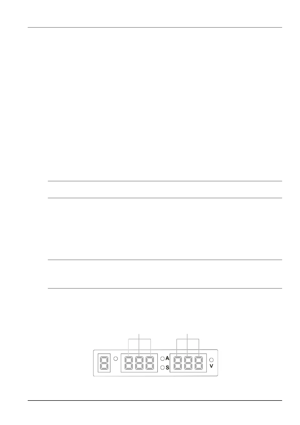
Figure 4-1 shows the screens and indicators.
Three nixie tubes in
the middle screen
Three nixie tubes in
the right screen
Job No.
Figure 4-1 Schematic diagram of screens