Chapter 4 Maintenance 67
Ehave Series Full Digital IGBT CO
2
/MAG/MMA Multifunctional Inverter Welder User Manual
Table 4-5 describes the welder error codes as well as causes and solutions.
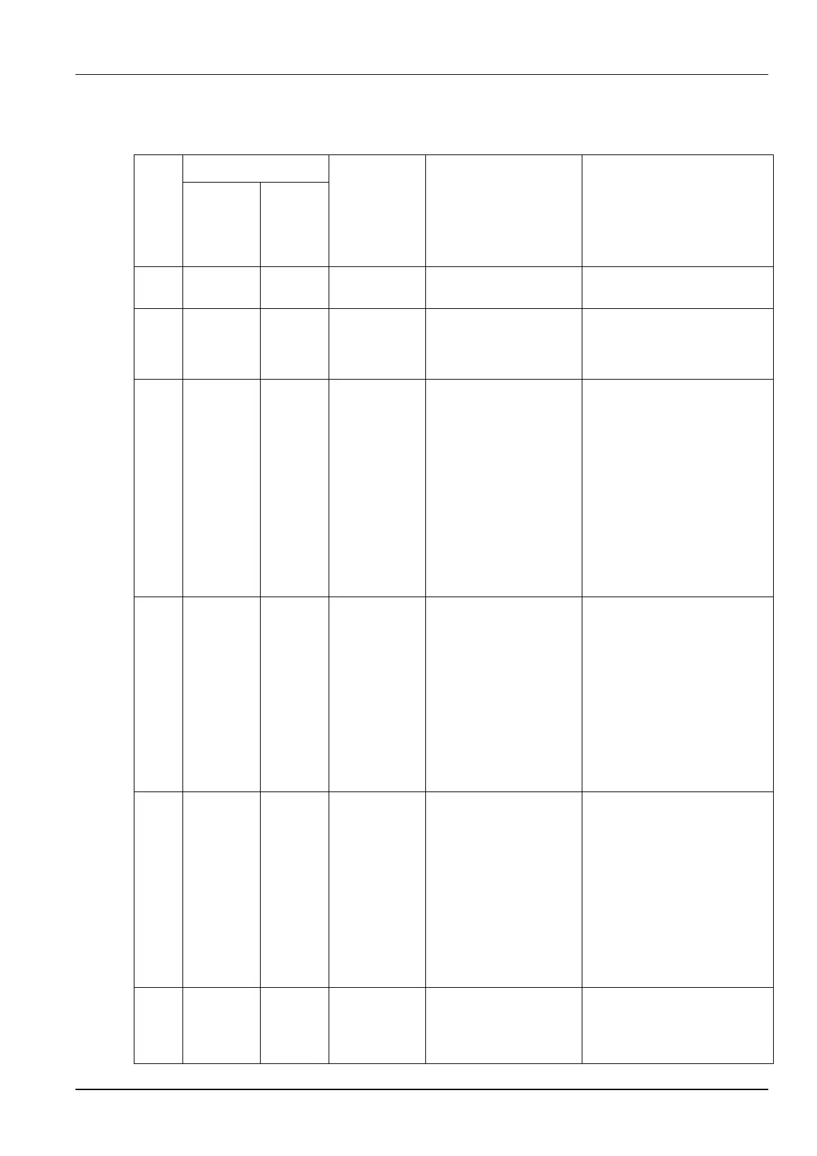
Table 4-5 Welder faults, causes, and solutions
Three
Nixie
Tubes in
the Middle
Screen
Three
Nixie
Tubes in
the Right
Screen
When the welder is
turned on, the welding
torch power switch is on.
The switch is broken.
Turn off the switch.
Replace the welding torch.
Output
terminal
over-temperat
ure
The output terminal and
power cable are
disconnected or the
screw is not fastened.
The copper
cross-sectional area of
the output power cable is
too small.
The output cable terminal
fails to meet the
specification requirement.
The fan does not work or
slows down.
Reliably fasten the output
terminal.
Use cables with greater
cross-sectional areas.
Select suitable cable terminals.
Verify that the fan works
properly.
The input power cable is
not connected properly.
Input power overvoltage
occurs.
Input power undervoltage
occurs.
Input power phase
imbalance occurs.
The input power
frequency exceeds the
range.
Verify that the input cables are
connected properly.
Verify that the input power is
normal.
IGBT or diode
over-temperat
ure
The rated duty cycle is
exceeded.
The air vent of the
housing is blocked.
The radiator is covered
with heavy dust.
The fan does not work or
slows down.
The IGBT or diode
current is excessively
high.
Ensure that the welder works
within the rated duty cycle
range.
Verify that the air vent of the
welder is not blocked.
Remove dust from the radiator.
Verify that the fan works
properly.
Verify that the main power board
and output diode module are
normal.
A button is jacked up.
A button does not
rebound after being
pressed.
Check the buttons
corresponding to the numbers
(displayed on the right screen)
shown in Figure 3-1.