Chapter 2 Installation and Cabling 21
Ehave Series Full Digital IGBT CO
2
/MAG/MMA Multifunctional Inverter Welder User Manual
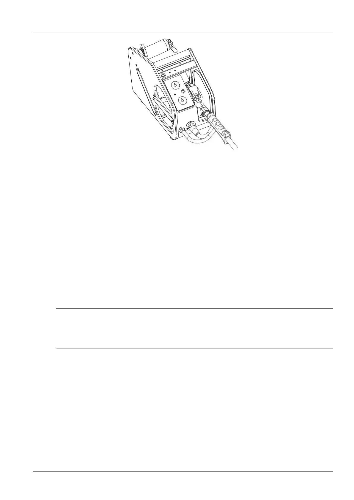
Figure 2-9 Schematic diagram of connecting the welding torch to the wire feeder
2.6.5 Connecting the Welding Power Cable (Grounding Cable) on the
Workpiece Side
On the workpiece side, connect one end of the welding power cable to the workpiece and
ground the workpiece properly with a cable.
2.6.6 Connecting the Power Cable on the Power Input Side
1. Turn off the power switch of the distribution box (user equipment).
2. Remove the input terminal cover. See Figure 2-10.
3. Connect one end of the input power cable to the power input terminal and use the power
cable clamp to fix the cable on the rear plate of the welder. Connect the grounding cable to
the M6 grounding threaded rod on the housing of the welder.
Note
The welder has no special requirement for the phase sequence of the three-phase power supply from the
grid. The cross-sectional area of the input power cable for Ehave CM250/350/350AR must be at least
10 mm
2
. The cross-sectional area of the input power cable for Ehave CM500/500H/500AR must be at
least 16 mm
2
.
4. Install the input terminal cover.
5. Connect the other end of the input power cable to the output terminal of the power switch of
the distribution box.