Chapter 2 Installation and Cabling 17
Ehave Series Full Digital IGBT CO
2
/MAG/MMA Multifunctional Inverter Welder User Manual
2.6.1 Welder Output Cables
The procedure for connecting the positive and negative output terminals with the welding power
cables of the wire feeder and workpiece is as follows:
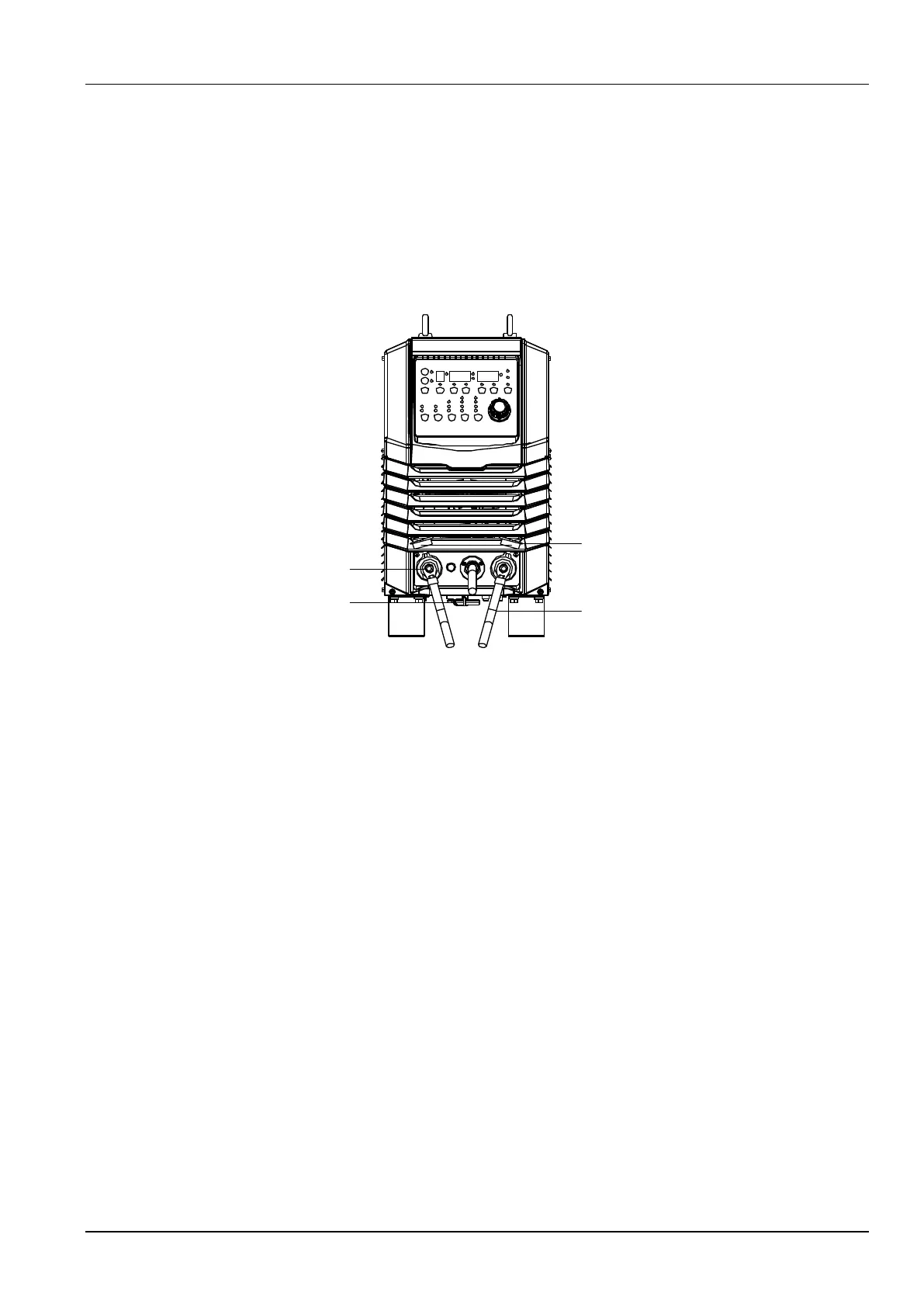
1. Remove the protective cover of the output terminals. (See Figure 2-3.)
2. Take out the hex key from the bottom of the welder. See Figure 2-3.
M10 nut
Hex key
Output power cable
Input terminal
protective cover
Figure 2-3 Schematic diagram of connecting the positive and negative output terminals
with the welding power cables of the wire feeder and workpiece
3. Remove the M10 nuts of the output terminals.
4. Fasten the power cable in the cable bundle and the M10 ring terminal of the welding power
cable of the workpiece to the positive output terminal and negative output terminal
respectively.
5. Use the hex key to fasten the M10 nuts and put the hex key back.
The procedure for connecting the 7-core jack of the wire feeder to the 7-core control cable of
the wire feeder is as follows:
1. Connect the 7-core aviation plug of the cable bundle to the 7-core jack on the welder.
2. Rotate the screw cap of the plug clockwise to fasten it.
3. Figure 2-4 shows the cable connections.