Chapter 3 Welder Operation Description 59
Ehave Series Full Digital IGBT CO
2
/MAG/MMA Multifunctional Inverter Welder User Manual
Wire inching signal
(forward wire inching)
I/O signal provided by a welding robot to the
welder to enable the wire inching motor to
perform forward wire inching. It is effective in
case of a low level.
I/O signal provided by a welding robot to the
welder to control the gas solenoid valve. It is
effective in case of a low level.
Analog signal provided by the robot to the
welder to indicate the preset voltage value.
Analog signal provided by the robot to the
welder to indicate the preset current value.
Analog signal provided by the welder to the
robot to indicate the actual welding voltage
value.
Note 1: The robot provides a 24 V power supply for the welder. It must range from 20 V to 30 V.
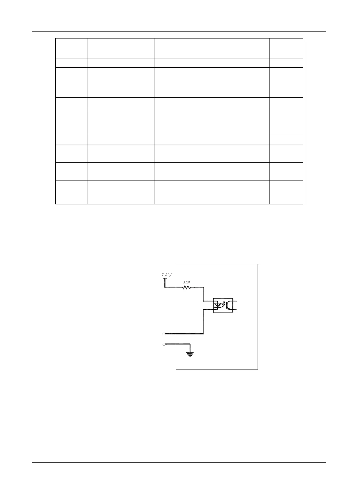
Note 2: Figure 3-42 shows the equivalent circuit for I/O signal transmission from the robot to the welder. It is effective
when the level is low. As shown in the figure, if the voltage between the positive and negative terminals for the I/O
signals ranges from 0 V to 5 V, the level is low and the robot performs operations. If the voltage ranges from 18 V to
24 V, the level is high and the robot does not perform operations. The voltage for I/O signals ranges from 0 V to 30 V.
24 V
Equivalent circuit within
the welder
-
+
Welding robot
I/O signal
Figure 3-42 Equivalent circuit for I/O signal transmission from the robot to the welder
Note 3: Figure 3-43 shows the equivalent circuit for starting arc generation success I/O signal transmission from the
welder to the robot. It is effective when the level is low. That is, when the optocoupler in the circuit shown in the
figure is disconnected and I/O signals are transmitted at a low level, starting arc generation is successful. When the
optocoupler is connected and I/O signals are transmitted at a high level, arc is not started. The loading capability of
the I/O signal ranges from 0 mA to 15 mA.