13 Image Vault
®
PRO Command
3.732Camera/240FPSModel:Video&AudioCapture,Moni-
tor Output
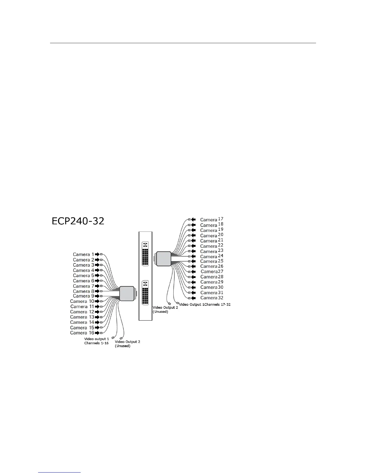
Video In: Connect up to 32 NTSC video cameras to the BNC connectors on the
video input breakout cables. The camera input breakout cables are connected to
the DVI ports to the left. The bottom DVI connector inputs are for cameras 1 to
16. The top DVI connector inputs are for cameras 17 to 32.
Audio In: The audio connection for the 32/240 is the same card as the
16/480. Connect up to 16 line level audio microphones to the RCA connectors
on the microphone breakout cables. Connect these breakout cables to the DB15
ports to the right. The bottom-right connector inputs are for Mic 1 to Mic 8. The
top-right connector inputs are for Mic 9 to Mic 16. Each microphone input is as-
sociated with 2 cameras. Audio input 1 = Camera 1+2, Audio input 2 = Camera
3+4, etc. (Audio diagram same as on page 12)
Video Out: One Public View Monitor (PVM) output is provided per 16 chan-
nel dongle. Video output 1 on each dongle will provide the cycling output that
will display the cameras on that dongle. (Video Output 2 is reserved for future
development)
3.8 IP/MegaPixel Cameras
Connection of IP/MegaPixel cameras requires some camera setup using software
providedbythecameramanufacturer.AfterconguringIP/MegaPixelcameras,
connect them to your LAN with the DVR. There are numerous limitations associ-
ated with IP cameras. Refer to PART II for more information.