14 Image Vault
®
PRO Command
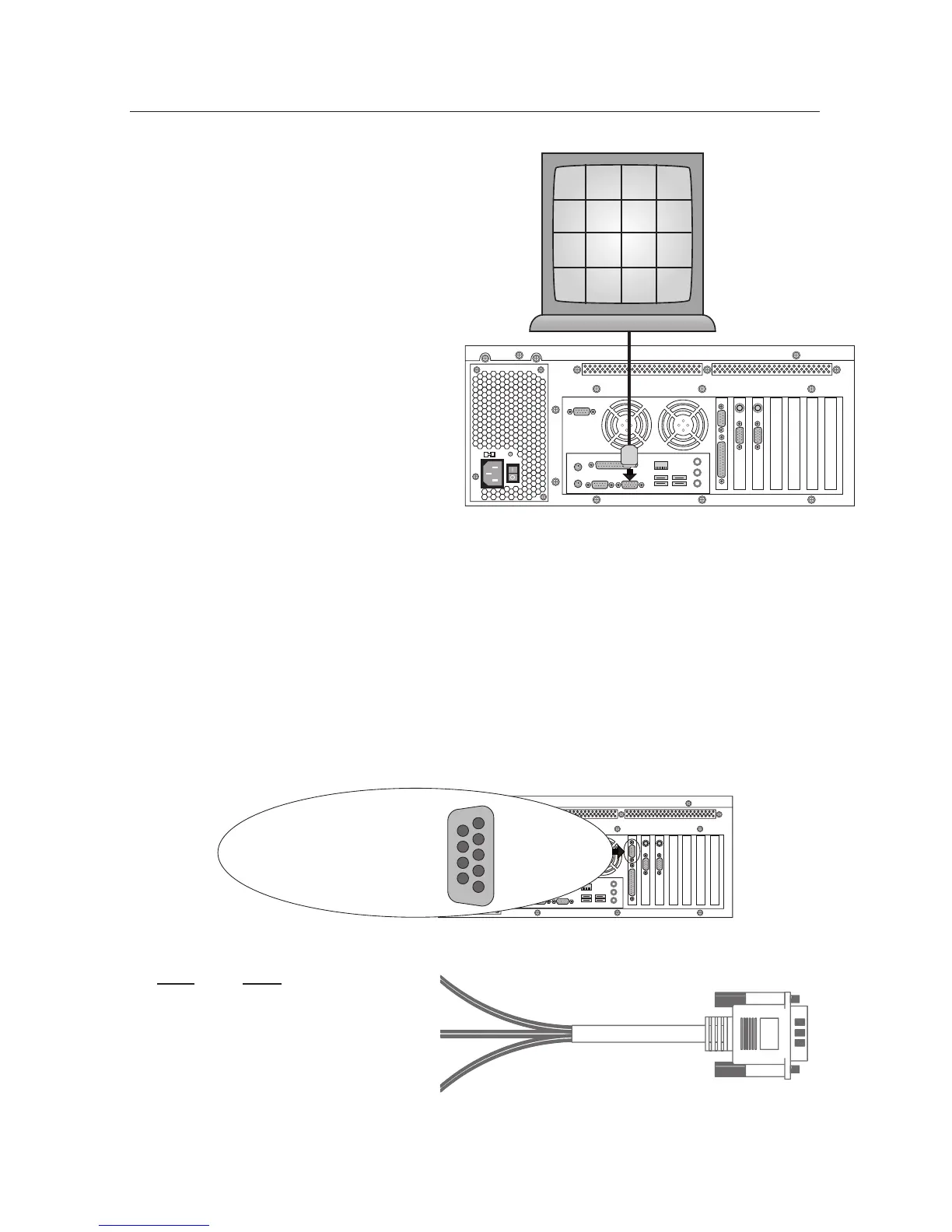
PTZAOC Wiring
Pin# Wire
2 Black
3 Red
6 Green
7 Brown
8 Orange
9 Yellow
Ground 1
RS485 TX– 2
RS485 TX+ 3
N/A
N/A
6 Alarm Contact Common
7 Alarm Contact N.O.
8 Watchdog Contact Common
9 Watchdog Contact N.C.
PTZ/Alarm Outputs
IV-PTZAOC Cable
DB9 Male
Connect to DVR
Watchdog Output
Orange N/C and
Yellow Common
Incident Output
Green N/O and
Brown Common
PTZ Control Output
Red TX+ RS485
Black TX– RS485
3.9 SVGA Video Output: Security Monitor
Image Vault will interface with al-
most any standard SVGA (800x600 or
1024x768) monitor. The SVGA monitor
output is generally used as the security
monitor. It may display various combi-
nations of cameras in the live monitor
mode. When a mouse is con-
nected to the DVR, you may also
use the VGA monitor to review
recorded images, set up software,
or check status. Selected cameras
may be hidden from the VGA
output via software setup.
3.10 PTZ Control /
Alarm Output
For space considerations, the alarm output and PTZ control output share the
same Female DB9 port on the rear panel. The IV-PTZAOC cable is provided with
your DVR for easy connection to your alarm system and PTZ cameras. Refer to
the diagrams below for more information about wiring. PTZ control is via RS485
TX+ and TX– only. Software includes code support for Pelco, Panasonic, Kalatel
and Sensormatic PTZ brands. The watchdog output follows a fault condition and
closes only when the DVR loses power or when the capture cards stop com-
municating with the CPU. The incident output is a momentary (about 1 second)
output triggered by the software’s Alarm Output feature. Watchdog and
incident relays are designed to handle a maximum of 30 V
AC/DC
and 1 Ampere.
Warning: Exceeding these ratings will damage the DVR and void the war-
ranty.
SVGA Monitor
CAM
1
CAM
2
CAM
3
CAM
4
CAM
5
CAM
6
CAM
7
CAM
8
CAM
9
CAM
10
CAM
11
CAM
12
CAM
13
CAM
14
CAM
15
CAM
16