9 Image Vault
®
PRO Command
3 Connecting System Components
Pick a level surface to place the Digital Video Recorder (DVR). The system should
have adequate ventilation and should be clear of moisture and dirt. The following
sectionsdetailsetupofspecicitems.
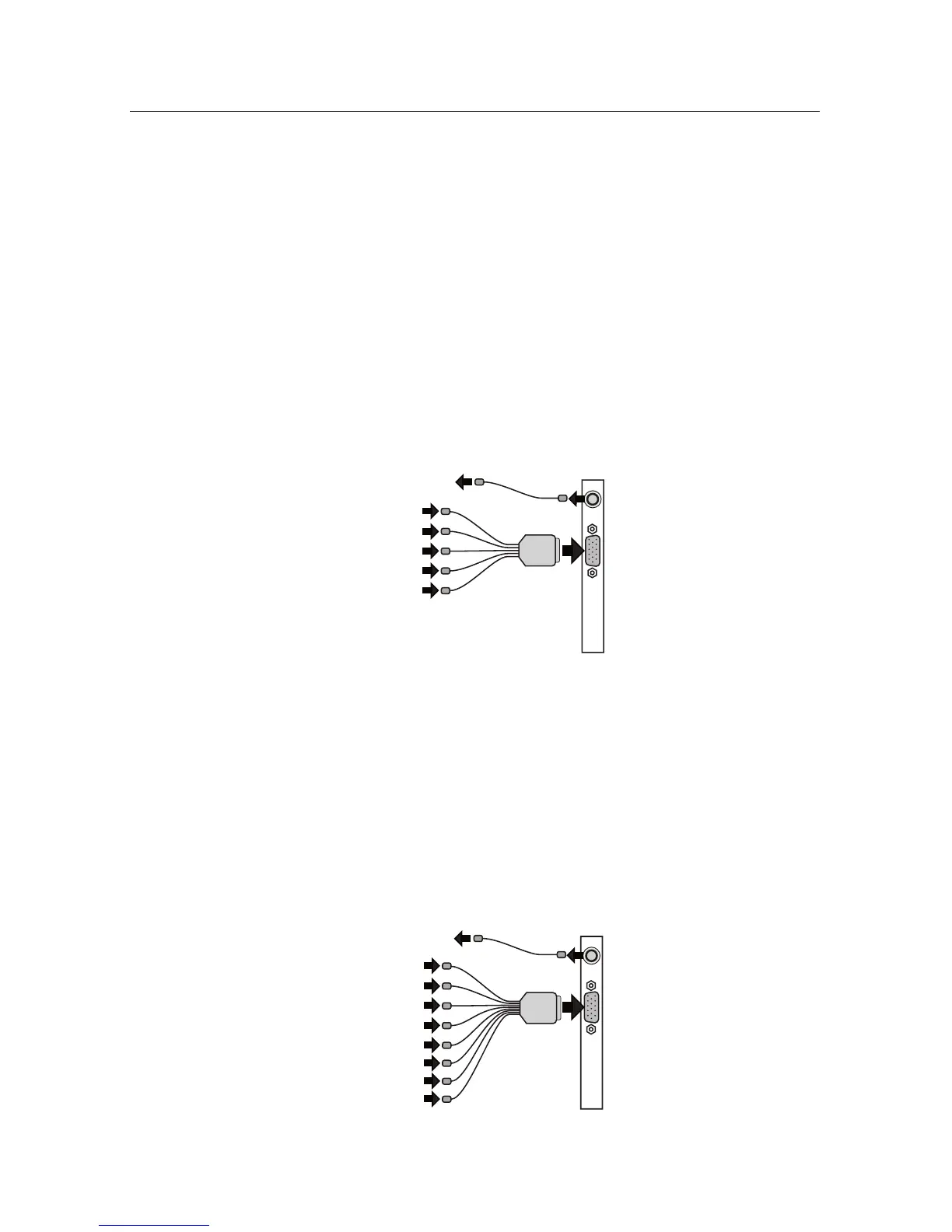
3.14Camera/30FPSModel:Video&AudioCapture,Monitor
Output
Video In: Connect up to 4 NTSC video cameras to the BNC connectors on the
main breakout cable. The breakout cable is connected to the DB15 port on the
rear of the DVR.
Audio In: Connect one line level audio microphone source to the RCA connector
on the breakout cable.
Video Out: Connect the NTSC Public View Monitor (PVM) to the RCA connector
on the rear of the DVR. The PVM output cycles between camera inputs.
Mic 1
PVM 1-4
Camera 1
Camera 2
Camera 3
Camera 4
3.24Camera/120FPSModel:Video&AudioCapture,Monitor
Output
Video In: Connect up to 4 NTSC video cameras to the BNC connectors on the
main breakout cable. The breakout cable is connected to the DB15 port on the
rear of the DVR.
Audio In: Connect up to 4 line level audio microphones to the RCA connectors
on the breakout cable.
Video Out: Connect the NTSC Public View Monitor (PVM) to the RCA connector
on the rear of the DVR. The PVM output cycles between camera inputs.