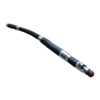
MICRO S automatic Cutter motor
2. Pull the spring contact PCB cable out of the air
motor housing.
1. After removing the old brush unit, prepare to solder
the new brush unit.
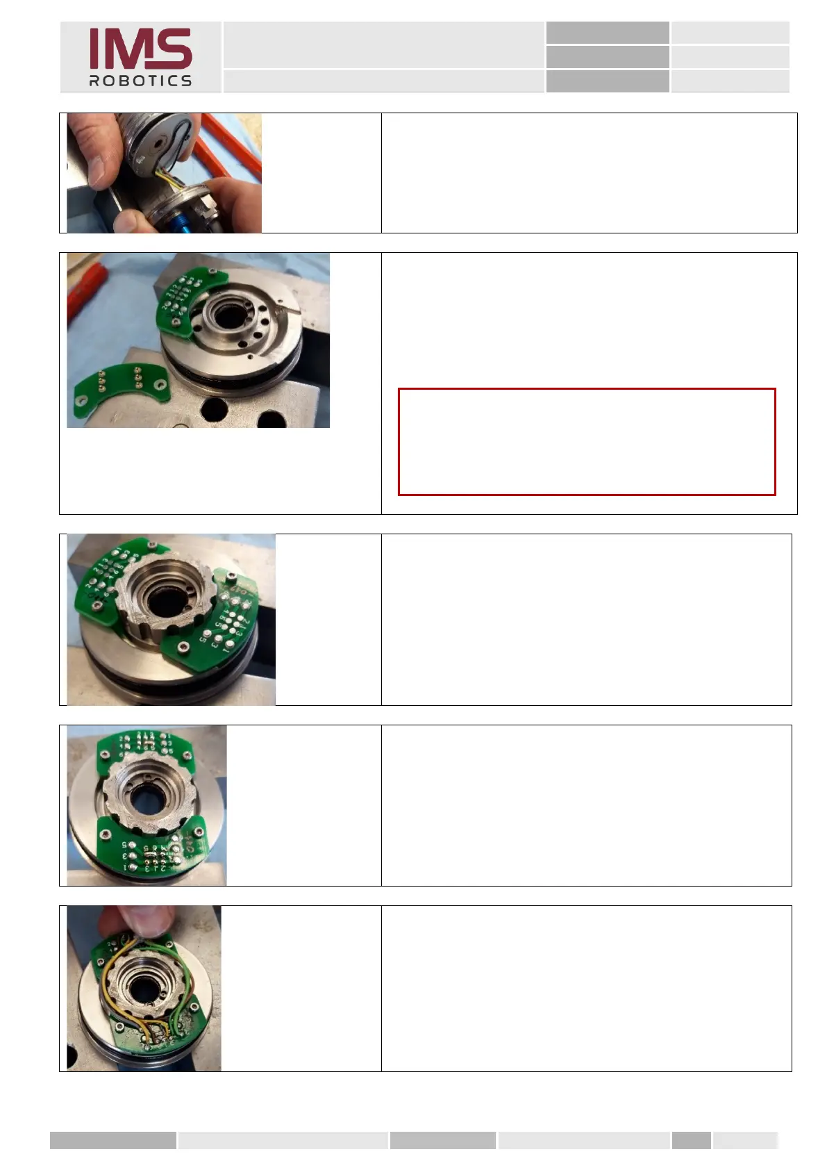
To do this, screw the two brackets upside down on
the front rotary unit. The solder joints have to point
upwards.
2. Place a tool for soldering the wires on the rotary
unit to bring the wires into the correct position for
soldering.
4. Cut the new camera cable to about 300 mm. Strip
one side by about 100 mm and adjust the wires so
that they can be wound around the ring and the
cable sheath starts again at the end of the ring.
5. Solder the wires as per the circuit diagram
Caution
When screwing the PCBs
insert spacers (e.g. nuts) under the PCBs. The contact
springs should not make contact with the rotary unit.