MICRO S automatic Cutter motor
18. Mounting the disc grinding ring
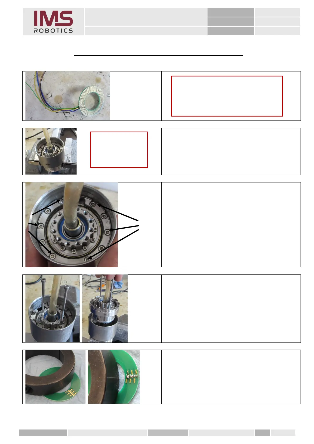
1. Clamp the rear rotary unit in a vice as
shown.
2. Remove the 6 M2.5x14 cylinder screws
marked on the left in the figure.
In each group of five there are the two
outer ones and the middle screw.
The other two hold the unit adapter
together and need not be loosened.
3. To help in removing the rotary unit,
insert two 3 mm screws or threaded rods
into the output flange and pull the rotary
unit upwards.
1. Fix the disc grinding ring for soldering
using a heavy object.
2. Over the contacts of the tracks
3 / 4 and 5 / 6 solder bridges.
Caution
To be able to install the wires of the new
disc grinding ring behind the rotary unit
again, it has to be removed from the
housing.
Caution
Use protective jaws
for the vice.