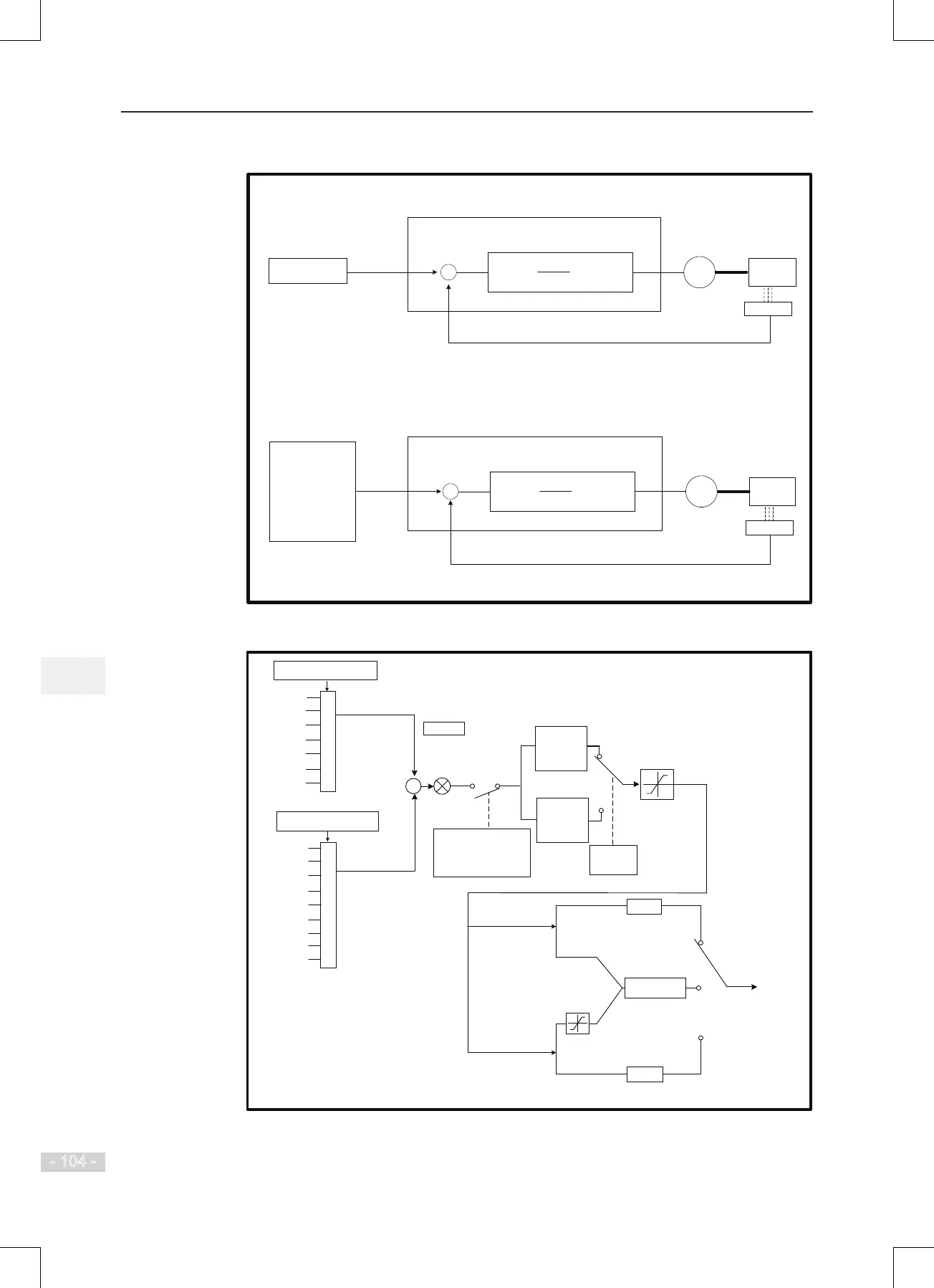
FA-00
PID reference setting channel
FA-02
PID feedback setting channel
1
2
3
4
5
6
FA-1
AI1
AI2
AI3
Serial comms.
Pulse reference
Multi-reference
1
2
3
4
5
6
AI1
AI2
AI3
Serial comms.
AI1 - AI2
AI1 + AI2
Pulse reference
7
8
Max. (|
AI1|, |AI2|)
Min. (|AI1|, |AI2|)
0
0
+
-
FA-03
1: Reverse
PID operation direction
0
: Forward
PID 1
FA-05: P gain 1
FA-06: I time 1
FA-07: D time 1
PID
2
FA-15:
P gain 2
FA-16: I time 2
FA-17: D time 2
Switchover
condition
FA-18
FA-19
FA-20
PID limit
F
0-10 in forward direction
FA-08 in
reverse direction
F0-05, F0-06
(Limit auxiliary for main
& auxiliary calculation )
Final
frequency
reference
Main
Auxiliary
Main & auxiliary
calculation
+
-
PID
switch
Any of F4-00 to F4-09 set
for function 22
: PID
disabled or PID deviation
smaller than FA-09 (PID
error limit)

 Loading...