2. Mechanical Installation
- 25 -
■
Stage 2: Preparing the Backplate for Hole Cut-out
● Refer to
T
a
b
l
e
2
-
1
to identify your model of the drive housing, and make a careful note
of the following dimensions:
● Mounting hole distances A and B
● Mounting hole diameter d
● Overall dimensions of the housing H and W
● Mark the backplate to identify the centers of the four mounting holes.
● Mark an outline for the cut-out by using the dimensions H and W. Ensure the cut-out
is centred with respect to the mounting holes.
● Carefully drill the four mounting holes.
● Carefully cut a rectangular cut-out hole in the supporting surface according to the
markings you made in step 6.
● Prepare edges of the cut-out to remove sharp edges and burrs.
■
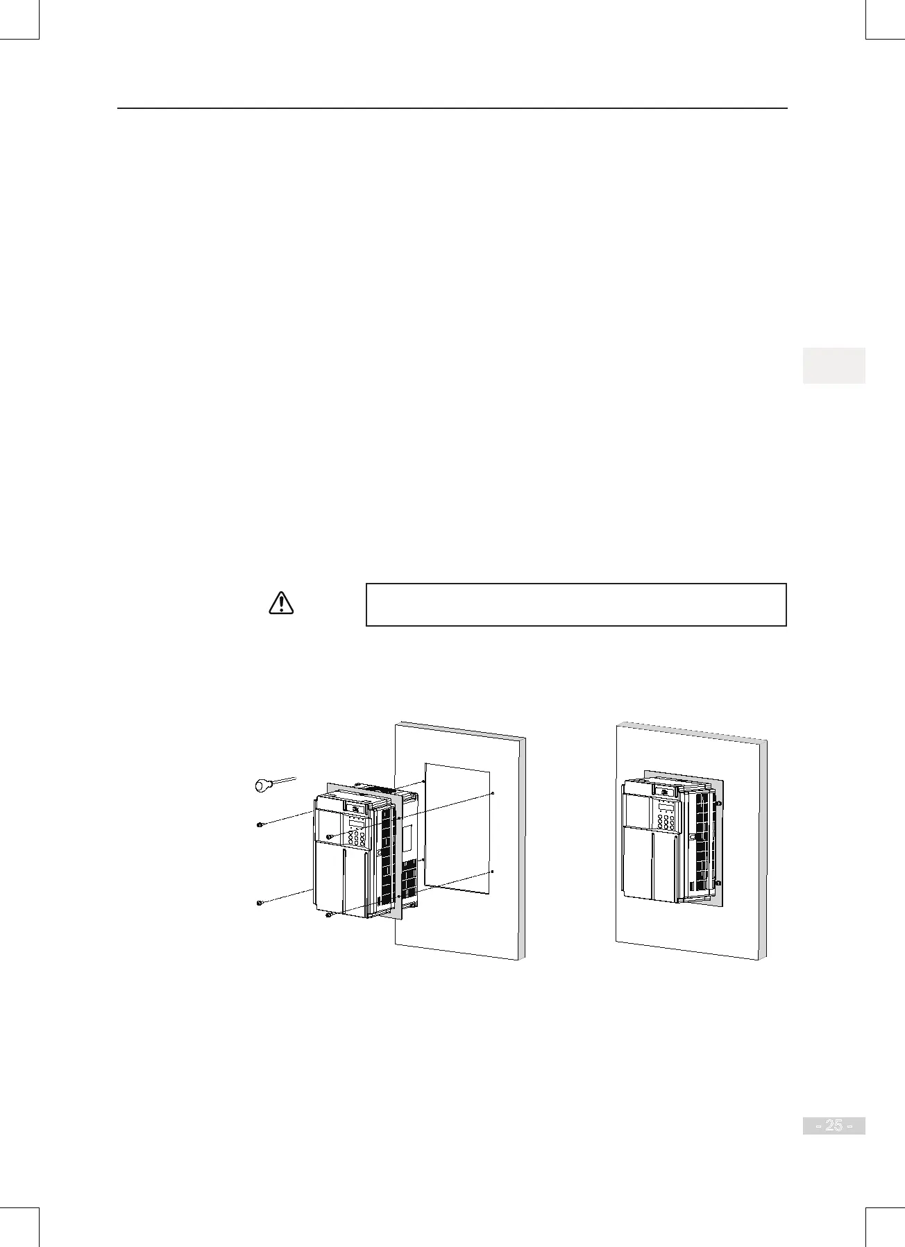
Stage 3: Installing the AC Drive into the Hole Cut-out
● Lift the AC drive into the cut-out you have prepared.
Insert the AC drive from the correct side of the mounting surface, depending on
whether you are using a front-mounting or a rear-mounting arrangement.
For the sheet metal housing, use a mechanical lift/device to support
the housing in its mounting location until you have xed it in place.
● Insert securing screws/bolts in the brackets, and secure the AC drive to the backplate.
Through hole installation of a plastic housing

 Loading...