3. Electrical Installation
- 43 -
3.3 Control Circuit Wiring
3.3.1 Control Circuit Terminals
■
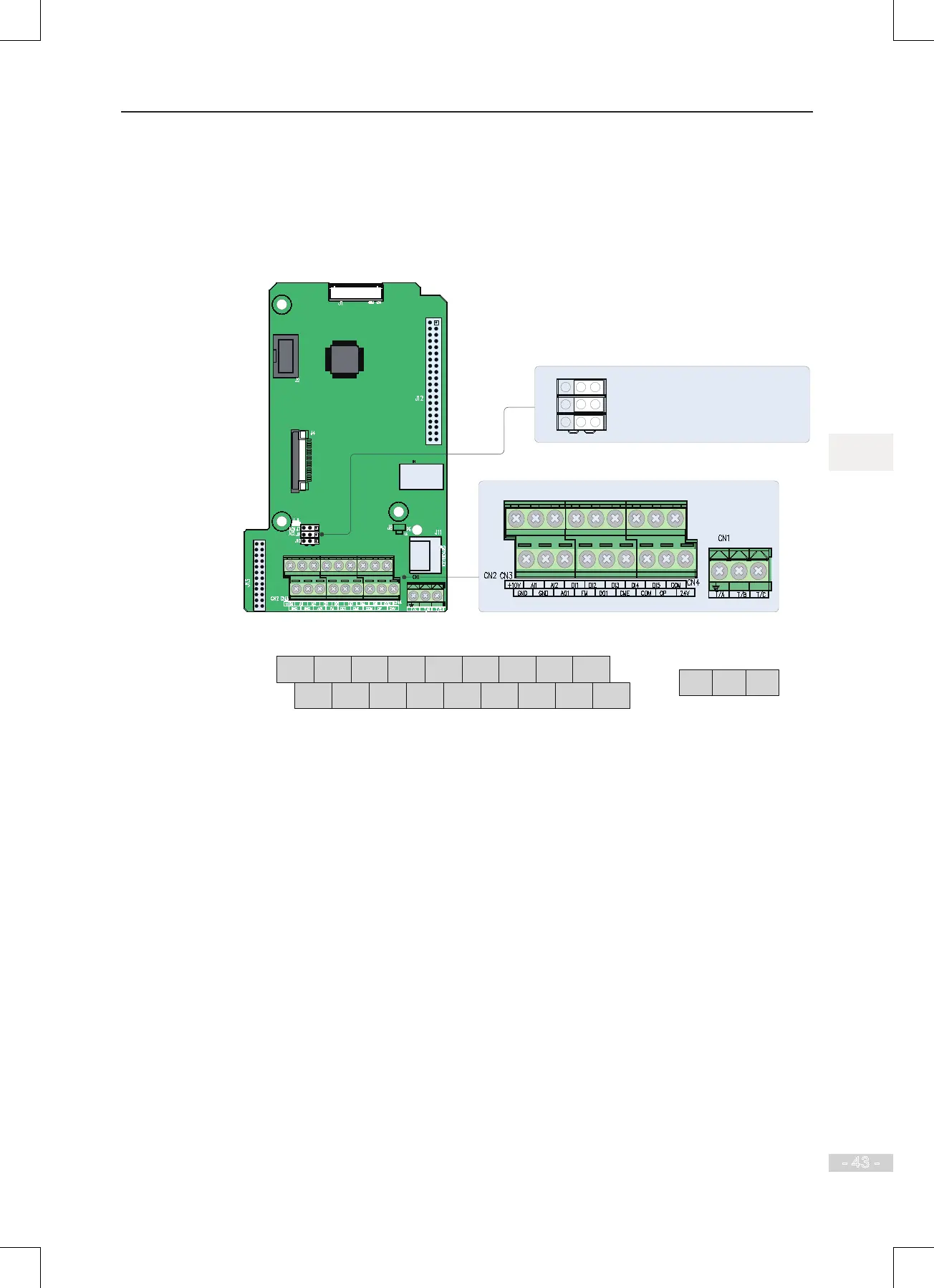
Terminal Arrangement
Figure 3-8 Control circuit terminal arrangement
AO1 output selection: voltage output by default
J7
J9
J10
I V
AI2 input impedance selection: 500Ωby default,
250Ω selectable
AI2 input selection: voltage input by default
The terminals are arranged as follows:
+10V AI1 AI2 DI1 DI2 DI3 DI4 DI5 COM
GND GND AO1 FM DO1 CME COM OP +24V
T/A T/B T/C

 Loading...