3. Electrical Installation
- 39 -
■
DC Bus Terminals
● DC bus terminals, labeled (+) and (-), are terminals that carry a residual
voltage for a period after the drive has been switched off.
● To avoid risk of equipment damage or re, when you select an external
braking unit for use with an AC drive of 90 kW and above, DO NOT
reverse the poles (+) and (–).
● Use a cable not exceeding10 m to connect DC bus terminals to external
MDBUN braking unit. Use twisted pair wires or close pair wires for this
connection.
● Fire risk! Do not connect braking resistor directly to DC bus.
■
Braking Resistor
● Fire risk! Fit overtemperature sensors or thermal overload relay to
the braking resistor, and use double insulated cables for the dynamic
brake circuit to the brake resistors.
● Braking resistor terminals (+) and PB are only for the drive units up to
75 kW that are tted with an internal braking unit.
● To avoid risk of equipment damage, use a cable not exceeding 5 m to
connect an external braking resistor.
● To avoid risk of ignition due to overheating of the braking resistor, do
not place anything combustible around the braking resistor.
● Set F6-15 (Braking use ratio) and F9-08 (Braking unit action initial
voltage) correctly according to load after connecting braking resistor to
the drive of up to 75 kW that is tted with an internal braking unit.
■
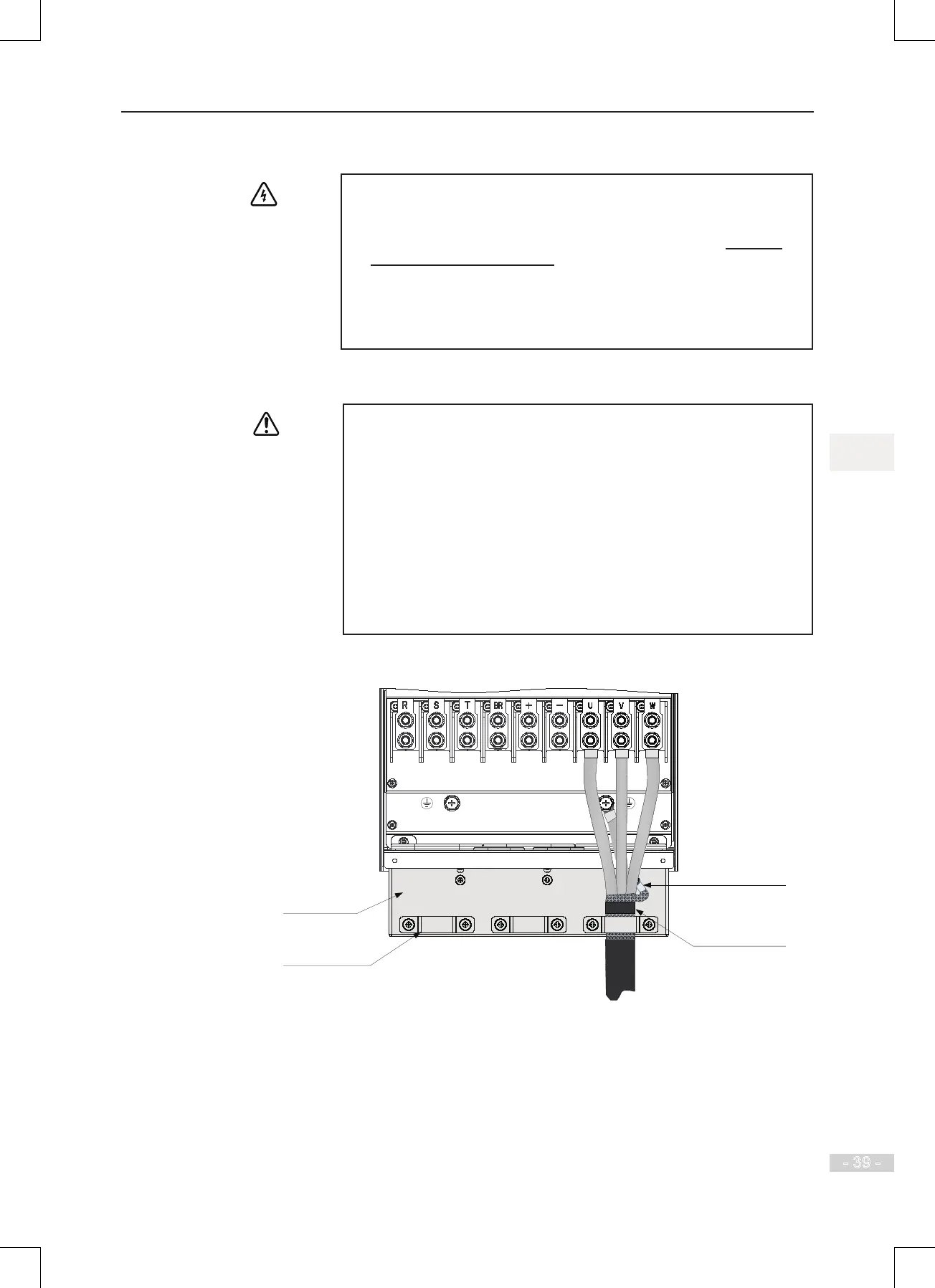
AC Drive Outputs U, V, W to Motor
Grounding clamp
for screen/shield
Main circuit cables
Cable support
bracket (option)
Use heatshrink tube or
insulation tape to terminate
the screen/shield.
Screen/shield

 Loading...