8. Peripherals and Options
- 233 -
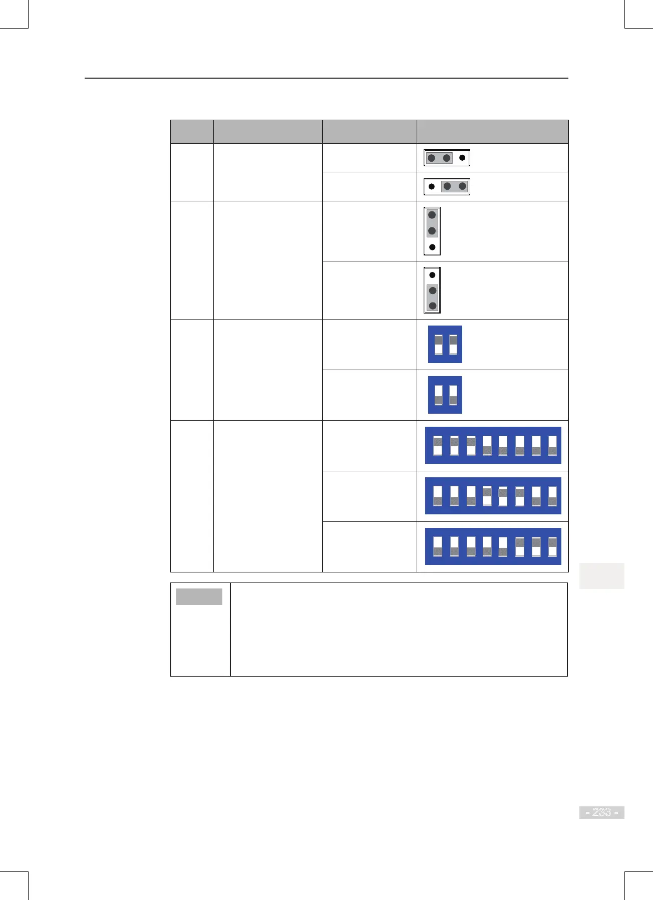
Table 8-2 Jumper descriptions of MD38IO1
Jumper Description Meaning Setting
J3 AO2 output selection:
voltage or current
Voltage: V to 10 V
Current: 0 to 20 mA
J4 CAN terminal resistor
matching selection
Matching terminal
resistor
Not matching
terminal resistor
S2 RS485 terminal
resistor matching
selection
1 and 2 set to ON:
matching terminal
resistor
1 and 2 set to
OFF: not matching
terminal resistor
S1 AI3, PT100, PT1000
selection
AI3: 1, 2, 3 set to
ON
PT1000: 4, 5, 6 set
to ON
PT100: 6, 7, 8 set
to ON
● Setting of jumpers takes top view with main terminals at the bottom of the
card as visual angle. Jumpers are silk-screened on the card.
● When using CANlink or Modbus protocol for communication, match
terminal resistor to the end AC drives by setting jumpers J4 or S2. The
J4 or S2 of the middle AC drives must keep default state. If J4 or S2 is
set improperly, instable communication or communication failure will
be caused and Err16 or Err55 will be detected.

 Loading...