6. Description of Parameters
- 88 -
■
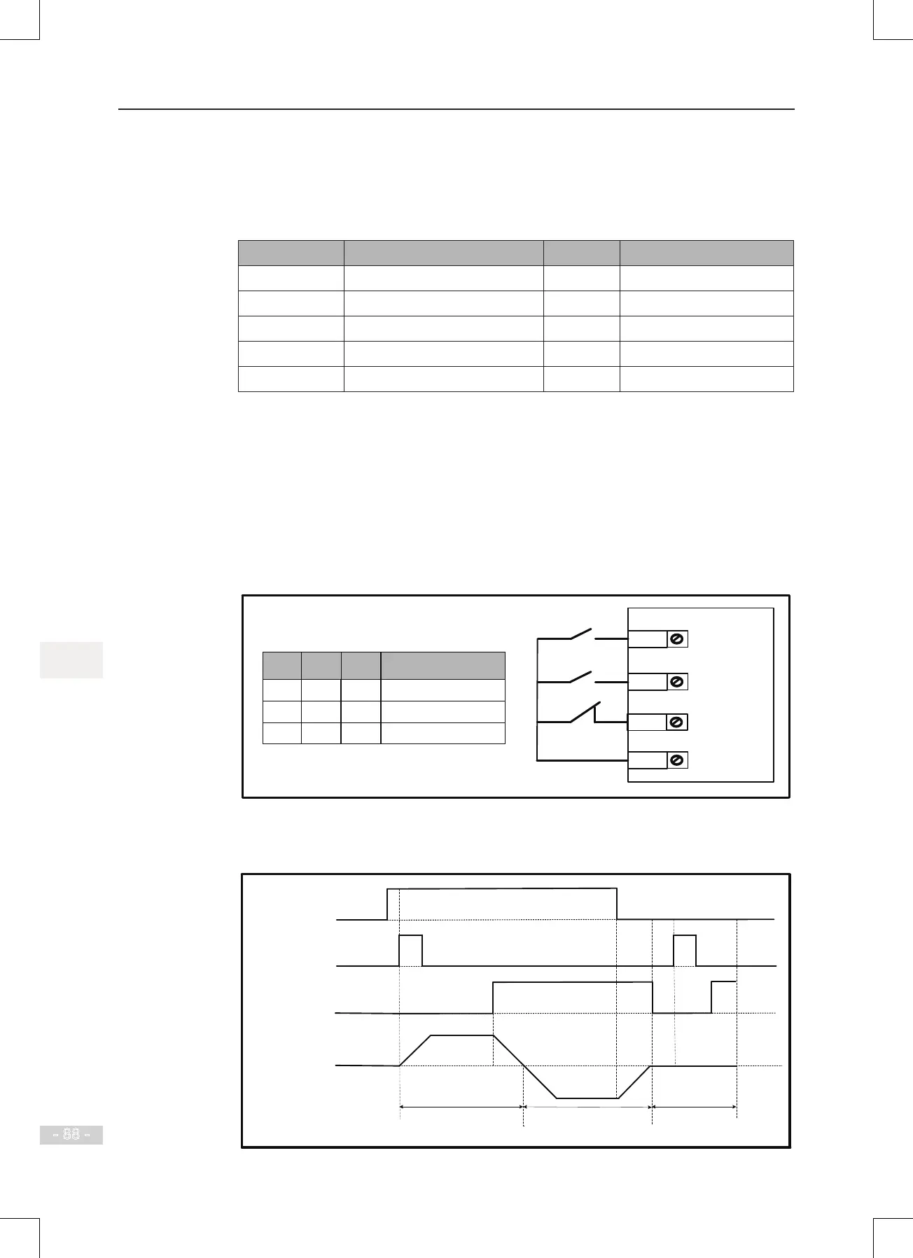
F4-11 = 3: Three-wire Control Mode 2
In this mode, DI3 is three-wire control command terminal. DI1 determines whether the
RUN command is enabled and DI2 determines running direction.
The parameters are set as below:
Function Code Parameter Name Value Function Description
F0-02 Command source selection 1 Terminal I/O control
F4-11 Terminal I/O control mode 3 Three-wire control mode 2
F4-00 DI1 function selection 1 Forward RUN (FWD)
F4-01 DI2 function selection 2 Reverse RUN (REV)
F4-01 DI2 function selection 3 Three wire control
SW3 is a normally-closed button and SW1 and SW2 are normally-open buttons.
● SW3 must remain closed during start sequence and during normal run operation.
● Motor stops immediately when SW3 opens.
● Signals from SW1 and SW2 are valid only with SW3 closed.
● On normal condition (SW3 closed), after you press down SW1, motor rotates in
forward direction with SW2 open. Motor rotates in reverse direction with SW2 closed.
Figure 6-9 Three-wire 2 sequence wiring diagram
DI1
Three-wire control
Run enabled
DI2
COM
Running direction
DI3
SW1
SW2
SW3
0/1
1
1
0/1
0
1
Running Command
Stop
Forward
Reverse
SW2SW1
0
1
1
SW3
The timing diagram of the three-wire control mode 2 is shown in the following gure.
Figure 6-10 Three-wire 2 sequence
Motor speed
Stop
SW2 off
SW2 on
SW1 (run
Enabled command)
Motor rotates in
forward direction
Motor rotates in
reverse direction
SW
3 (three-wire
control command)
SW2 (forward/
reverse direction)

 Loading...