Wiring
‑129‑
Use a three‑conductor shielded cable to connect the RS485 bus, with the three
conductors connected to 485+, 485‑, and GND (GND represents non‑isolated RS485
circuit) respectively. Connect 485+ and 485‑ with two conductors twisted together
and connect the remaining conductor to RS485 reference ground. Connect the shield
to the device ground PE. Connect a 120 Ω termination resistor on each end of the bus
to prevent RS485 signal reflection.
Table 3–35 Pin connection relation of the cable used for RS485 communication between
the servo drive and PLC
RJ45 on the Servo Drive Side (A) PLC Side (B)
Communica
tion Type
Signal Name
Pin No.
Communica
tion Type
Signal Name
Pin No.
RS485
485+ 4
RS485
485+ 4
485‑ 5 485‑ 5
GND 8 GND 8
‑
PE (shield)
Enclosure
‑
PE (shield)
Enclosure
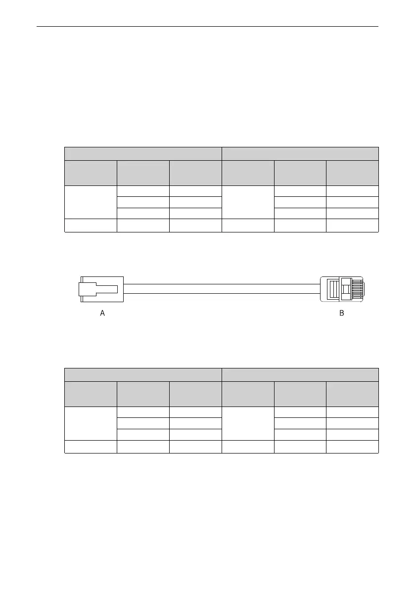
Wiring of multi-drive RS485 communication
The following figure shows the cable used for multi‑drive RS485 communication.
Figure 3‑42 Outline drawing of the cable used for multi‑drive RS485 communication
Table 3–36 Pin connection relation of the cable used for multi‑drive RS485 communication
(pins in 485 group used only)
RJ45 on the Servo Drive Side (A) RJ45 on the Servo Drive Side (B)
Communica
tion Type
Signal Name
Pin No.
Communica
tion Type
Signal Name
Pin No.
RS485
485+ 4
RS485
485+ 4
485‑ 5 485‑ 5
GND 8 GND 8
‑
PE (shield)
Enclosure
‑
PE (shield)
Enclosure
In case of a large number of nodes, connect the RS485 bus with the daisy chain mode.
Connect the reference grounds of RS485 signals of all the nodes (up to 128 nodes)
together.

 Loading...


