EasyManuals Logo

Inovance SV660P Series User Manual

Inovance SV660P Series
156 pages
To Next Page IconTo Next Page
To Previous Page IconTo Previous Page
Page #124 background imageLoading...
Page #124 background image
Wiring
‑123‑
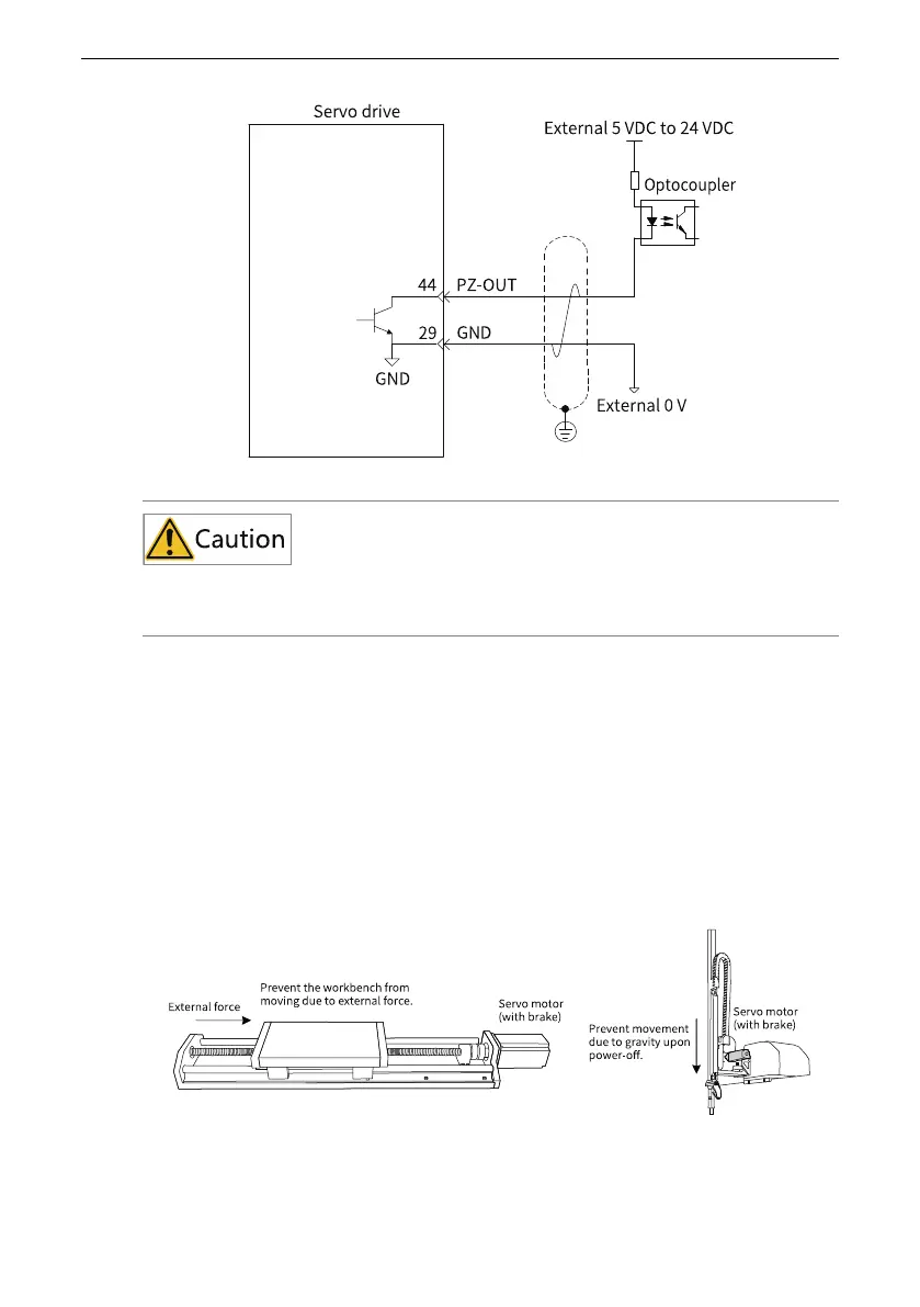
To reduce noise interference, use shielded twisted pairs to connect the 5V GND of the host
controller to the GND of the servo drive.
The maximum permissible voltage and current capacity of the optocoupler output
circuit inside the servo drive are as follows:
Maximum voltage: 30 VDC
Maximum current: DC 50 mA
3.8.5 Wiring of the Brake
The brake is used to prevent the motor shaft from moving and keep the motor and
the motion part in locked positions when the servo drive is in the non‑operating
status.
Figure 3‑35 Application of the brake

Table of Contents

Questions and Answers:

Question and Answer IconNeed help?

Do you have a question about the Inovance SV660P Series and is the answer not in the manual?

Inovance SV660P Series Specifications

General IconGeneral
Model/SeriesSV660P Series
CategoryServo Drives
Protection ClassIP20
Output Power7.5kW
Control ModeTorque, Speed, Position
Communication ProtocolCANopen, Modbus
Encoder FeedbackIncremental encoder, Absolute encoder
SafetySTO (Safe Torque Off)
Protection FeaturesOvervoltage, Undervoltage, Overcurrent, Overtemperature, Encoder error
Ambient Temperature0°C to 55°C
Humidity5% to 95% (non-condensing)
Vibration Resistance5.9 m/s²
Installation AltitudeUp to 1000m above sea level
Cooling MethodNatural cooling

Related product manuals