Wiring
‑117‑
The differential input must be 5 V. Otherwise, unstable pulse input will occur on the servo
drive, resulting in the following situations:
● Pulse loss during pulse input
● Reference inverted during reference direction input
Connect 5V GND of the host controller to the GND of the servo drive to reduce noise
interference.
3.8.3 DI/DO Signals
For description of DI/DO signals, see “
Table 3–8
”
on page 80
.
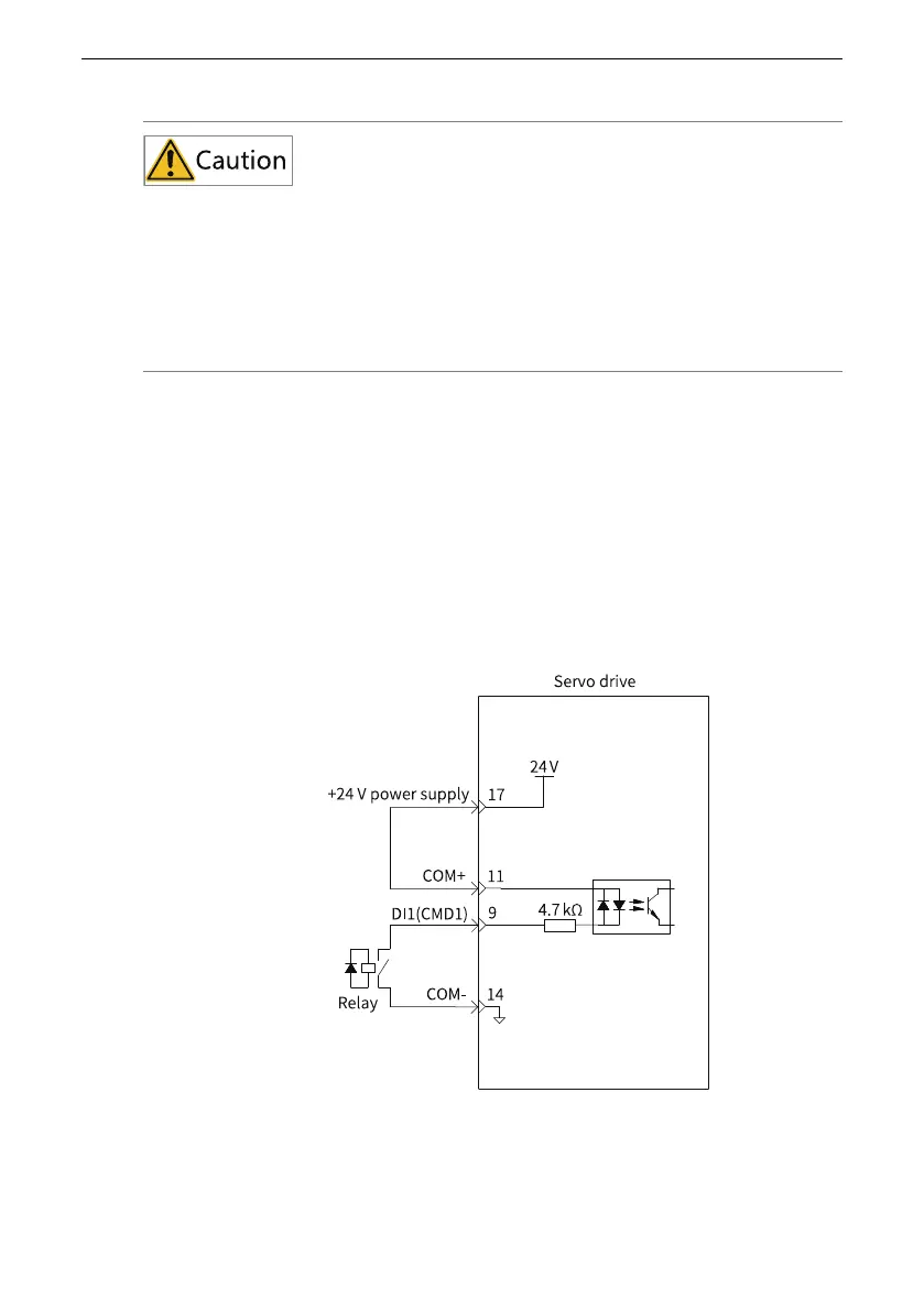
DI circuit
The circuits for DI1 to DI9 are the same. The following description takes DI1 circuit as
an example.
● The host controller provides relay output.
■ For use of an internal 24 V power supply of the servo drive
■ For use of an external power supply

 Loading...


