Product Information
‑24‑
No. Name
Description
5
L1C, L2C (control
circuit power input
terminals)
See the nameplate for the rated voltage class.
6
R, S, T (main circuit
power input terminals)
Used as the power input terminals for a three‑phase
380 V servo drive. See the nameplate for the rated
voltage class.
7
U, V, W (terminals for
connecting the servo
motor)
Connected to U, V, and W phases of the servo motor.
8
N2, N1 (terminals for
connecting external
reactor)
Terminals N1 and N2 are jumpered by default. To
suppress harmonics in the power supply, remove the
jumper between terminals N1 and N2 first and connect
an external DC reactor between terminals N1 and N2.
9
P⊕, D, C (terminals for
connecting external
regenerative resistor)
Remove the jumper bar between terminals P⊕ and D
before connecting an external regenerative resistor
between terminals P⊕ and C.
10
Battery location Used to hold the battery box of the absolute encoder.
11
CN1 (control terminal)
Used by reference input signals and other I/O signals.
12
CN2 (terminal for
connecting the
encoder)
Connected to the motor encoder terminal.
13
PE terminal
Connected to the grounding terminals of the power
supply and the motor for grounding purpose.
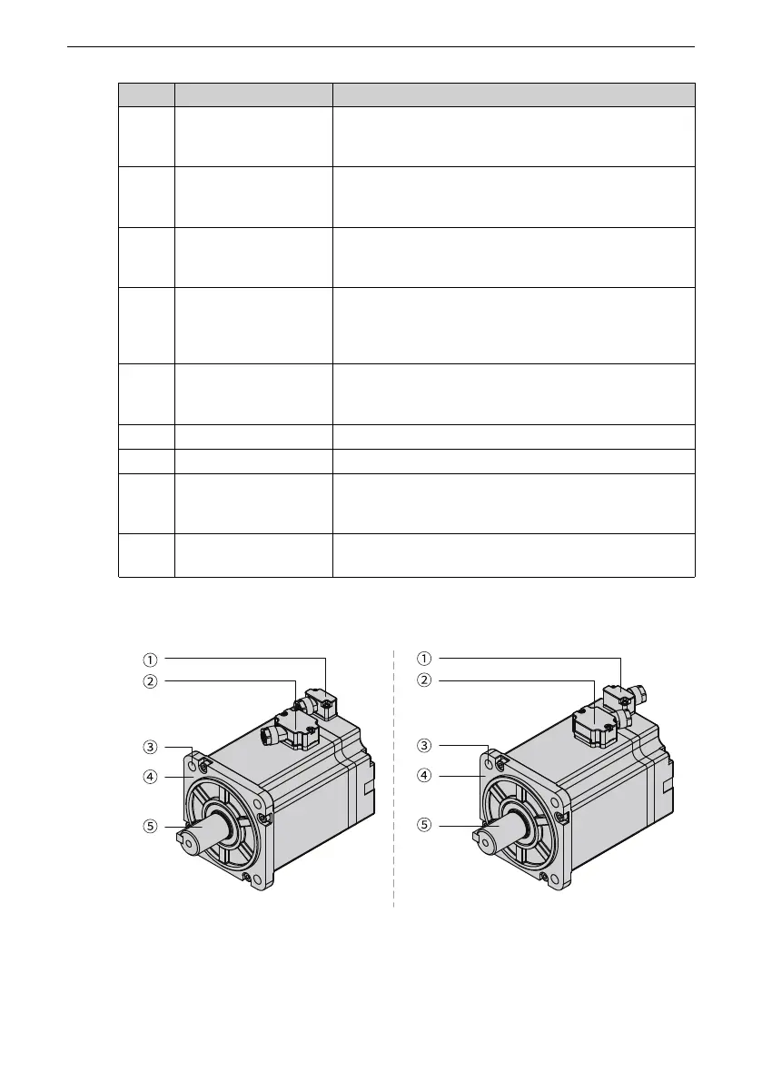
1.4.5 Servo Motors in Flange Sizes 40/60/80
Figure 1‑12 Components of terminal‑type motors (Left: motor with front cable outlet; Right:
motor with rear cable outlet)

 Loading...


