Wiring
‑77‑
Table 3–5 Description of main circuit terminal pins of servo drives in size E
No. Name
Description
1
L1C, L2C
(control circuit
power input
terminals)
See the nameplate for the rated voltage class.
2
R, S, T
(main circuit power
input terminals)
See the nameplate for the rated voltage class.
3
U, V, W
(terminals for
connecting the
servo motor)
Connected to U, V, and W phases of the servo motor.
4
N2, N1
Terminals for
connecting
external reactor
Terminals N1 and N2 are jumpered by default. To
suppress harmonics in the power supply, remove the
jumper between terminals N1 and N2 first and connect
an external DC reactor between terminals N1 and N2.
5
P⊕, D, C
(terminals for
connecting
external
regenerative
resistor)
If an external regenerative resistor is needed, connect it
between terminals P⊕ and C. Servo drives in size E are
equipped with the built‑in regenerative resistor, with
terminals P⊕ and D jumpered by default.
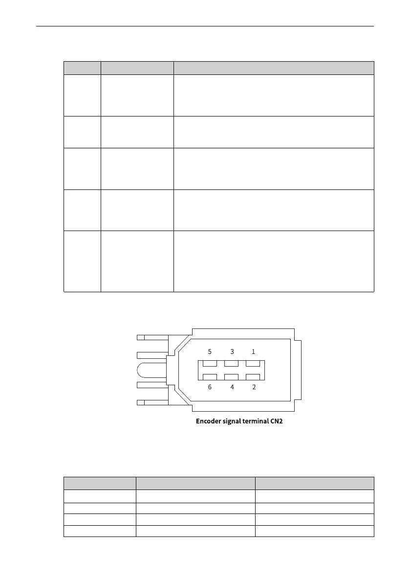
3.4.2 Description of Encoder Terminal (CN2)
Figure 3‑16 Encoder terminal pin layout
Table 3–6 Description of encoder terminal pins
No. Name
Description
1 +5V
5 V power supply
2 0V ‑
3
Reserved
‑
4
Reserved
‑

 Loading...


