Wiring
‑72‑
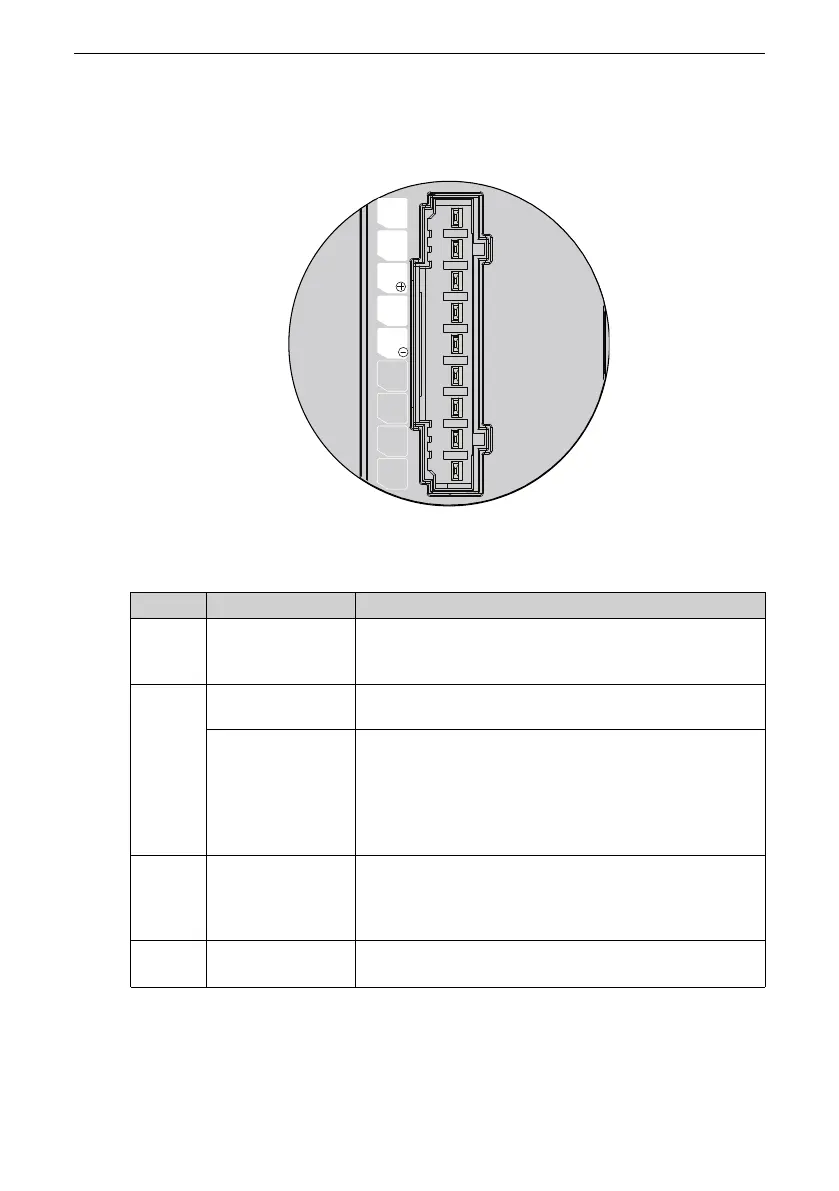
3.4.1 Main Circuit Terminal Pin Layout
Servo drives in size A (rated power: 200 W to 400 W): SV660PS1R6I and
SV660PS2R8I
Figure 3‑11 Main circuit terminal pin layout of servo drives in size A
Table 3–1 Description of main circuit terminal pins of servo drives in size A
No. Name
Description
1
L1, L2
(power input
terminals)
See the nameplate for the rated voltage class.
2
P⊕, NΘ
(DC bus terminals)
Used by the common DC bus for multiple servo drives.
P⊕ and C
(terminals for
connecting
external
regenerative
resistor)
If an external regenerative resistor is needed, connect it
between terminals P⊕ and C.
3
U, V, W
(terminals for
connecting the
servo motor)
Connected to U, V, and W phases of the servo motor.
4
Motor grounding
terminal
Connected to the grounding terminal of the motor for
grounding purpose.

 Loading...


